This is an old revision of the document!
Table of Contents
McDonnell Douglas F/A-18C Hornet
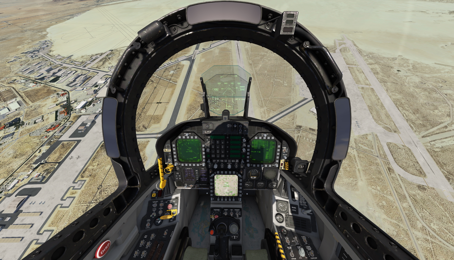
The F-18 by McDonnell Douglas is a twin-engine multi-role combat aircraft. It was developed in the 1970s and since 1983 it is in use. The F-18C of the Swiss Army is single-seated, as F-18D it exists also as two seated version. The two turbines give enormous performance of the machine. Thus, climbs of up to 50000 ft/min and a maximum speed at optimum altitude of Mach 1.8 are possible. The machine is controlled electronically by a fly by wire system. In order to increase the maneuverability, the machine was designed in a way that a control without this electronic support is not possible.
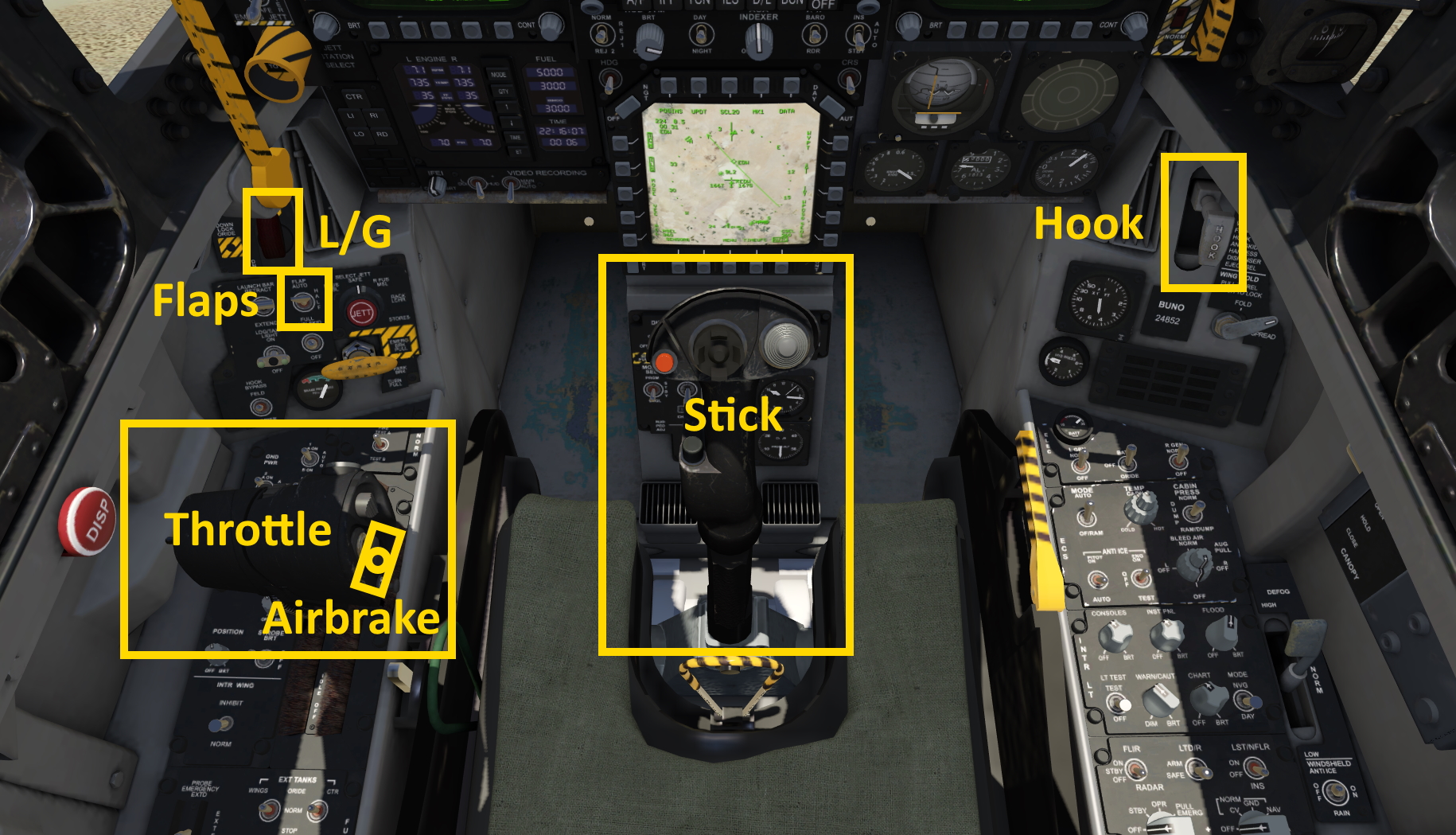
F18 Cockpit Introduction
Flight Controls
The F18 has two tailerons that are big rotating stabilizers in the tail section of the aircraft that combine the elevator and aileron controls. If they deflect symmetrically an elevator input is achieved, if they deflect asymmetrically a roll is induced.
There are also two regular ailerons on the wings, large trailing edge flaps and also leading edge flaps that work similarly to slats. But on the F18 these leading and trailing edge flaps can also deflect asymmetrically to increase maneuverability.
Last but not least: The F18 has two vertical stabilizers with rudders on each side. These rudders are deflected symmetrically for normal rudder operation and they deflect together with ailerons to increase the roll rate. They can also be deflected both inwards or outwards to increase elevator authority.
Fly By Wire Control
The F18 has a fly by wire system, which means the flight controls are processed electronically by computers which then compute the necessary control surface deflections to meet the commands of the pilot. In Aerofly FS this is simulated, your joystick inputs are processed and then redirected to the individual control surfaces.
With the flap selector in the AUTO position the stick the pilot commands a g-load target. He can command between negative 3gs and positive 7.5gs. When the stick is neutralized the aircraft will maintain 1g. In the real aircraft this means the aircraft would be pitching up when you fly straight up or down. In Aerofly FS this is currently not simulated, our F18 keeps flying straight when pointing up or down which makes it a bit easier to fly.
Flaps and Slats
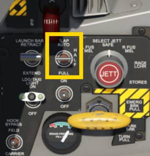
There are three positions that the pilot can select for the flaps and slats.
- AUTO: flaps and slats operate independently and asymmetrically based on many factors such as angle of attack, g-load and Mach-number. On high-g maneuvers the flaps and slats deflect down to increase lift. This decreases the turn radius. Slats deflect automatically at high angles of attack to increase the stall margin.
- HALF: flaps and slats deflect down to the half way position, depending on airspeed. Above 250kts they stay up. Below 250kts they gradually extend as speed decreases to maximize lift. The half position is selected for takeoff or approach.
- FULL: flaps and slats can deflect to the full position, again depending on airspeed. This position is selected for landing.
Approach Mode
With the flap selector on HALF or FULL the fly by wire enters the approach mode. The angle of attack is now also used by the fly by wire to steer towards the trimmed angle of attack. With the stick release the airplane starts to pitch up or down to regain the trim angle of attack.
Use the pitch trim commands to trim the aircraft during the approach.
When the aircraft is in the approach mode the throttle inputs affect the flight path. When you increase throttle and the aircraft eventually speeds up the aircraft will start climbing. When you decrease throttle the engine thrust decreases which slows the aircraft down and the fly by wire pitches down to stay at the trimmed angle of attack.
Use fine throttle changes to control the descent angle during final approach
This takes a bit of practice to get used to but this approach mode makes the aircraft behave more like an aircraft without fly by wire and feels quite naturally.
Airbrake
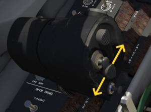
The speed-brake (or airbrake) is controlled with a gray rocker switch on the throttle lever. Use the mouse wheel over this switch to increase or decrease the airbrake position. With VR hands you can use your index finger to deflect the switch.
When the flaps are selected down the speed-brake will automatically retract. If you assigned a button for the extension of the airbrake then you have to keep holding the button to leave the airbrakes extended.
Multi-Function Displays (MFD)
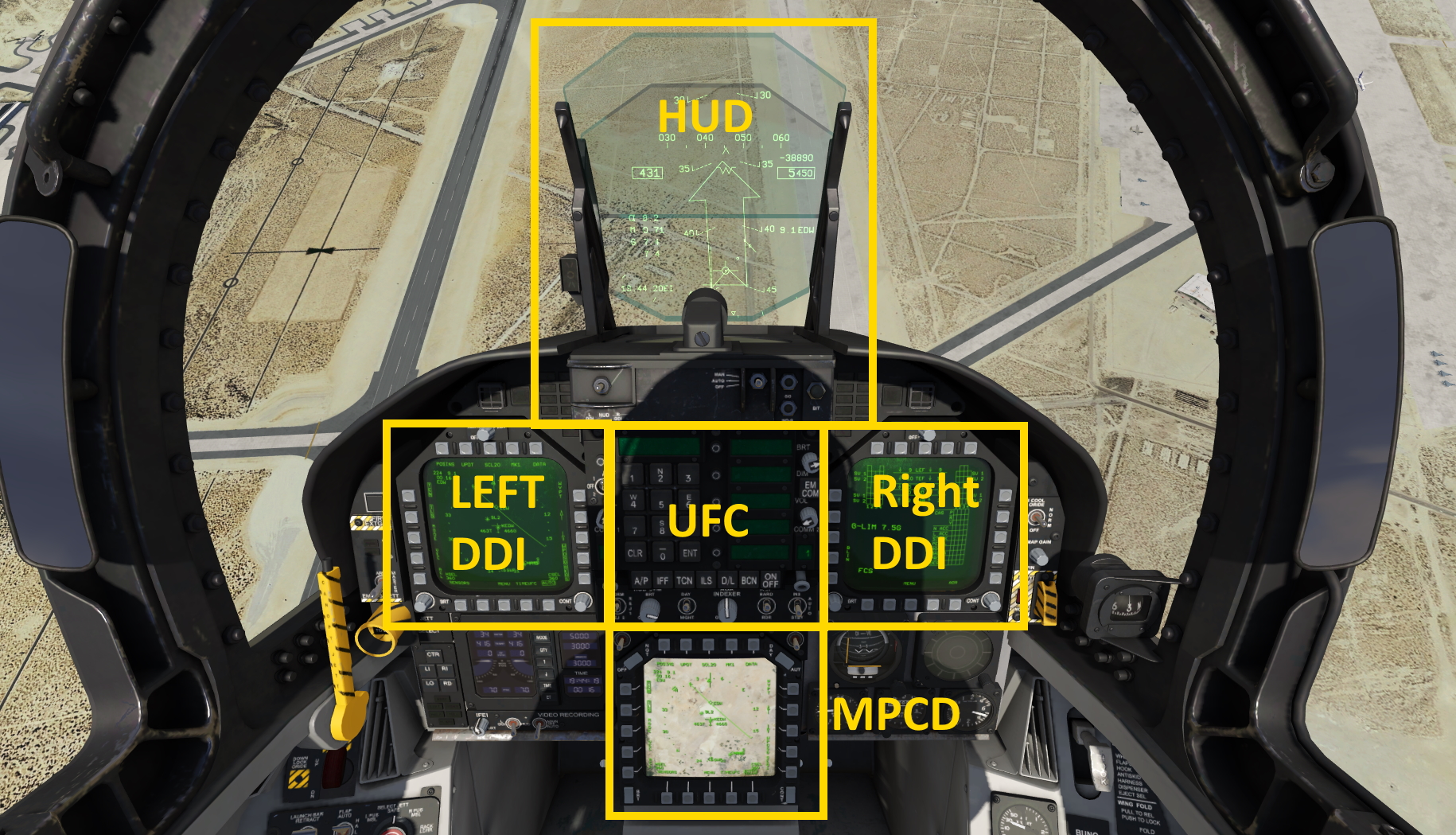
The F18 has three large screens: the left and right DDIs (digital display indicator) and lower mounted MPCD (multi-purpose color display). These can display various system pages ranging from attitude indicator (ADI), horizontal situation indicator (HSI) to engine, fuel, flight controls (FCS) to stores, radar display, waypoint information and other pages needed for warfare.
Menu System
The menu system is the same on all three main screens (DDIs and MPCD). On the row of buttons underneath the display press the center button, which is usually labeled “MENU”.
Press the MENU button once to access the tactical menu.
Press it a second time to access the support menu.
The tactical menu (TAC MENU) gives access to the stores, attack radar (ATTK RDR), head up display (HUD), target data (TGT DATA), electronic warfare (EW) and situation awareness (SA). Most of these pages are not yet implemented.
Press the menu button a second time to see the support menu. This menu allows you to select one of the following pages: horizontal situation indicator (HSI - already selected on the left DDI per default), backup attitude indicator (ADI), fuel, flight performance advisory system (FPAS), up front control backup unit (UFC BU), flight controls (FCU), engines (ENG), Checklists, built in test (BIT) and mission initialization (MUMI).
Simply click the button next to the page that you want to call. To return to the menu press the button in the middle of the center row again.
Note: The left and right DDI are logically connected. You can't select the same page on both sides. Attempting to do so will open the main menu on the opposite side. The lower display, the MPCD is independent.
Note: Only the MPCD can display a moving map in color. It can be deselected b pressing the MODE button on the left side.
HSI
The horizontal situation indicator (HSI) shows a top-down view of the aircraft's surroundings, navigation aids, waypoints, etc. Unlike typical HSIs or CDIs found in general aviation aircraft or even airliners the F18 HSI draws the radials through the TACAN or VOR station at the same scale as the displayed navaids, waypoints and moving map. This may look strange at first but it always shows the true relation of the aircraft to the station and radial and is quite easy to understand after a couple of minutes.
To change the zoom press the button in the middle of the top row, labeled “SCL” for scale. Press it multiple times to cycle through the zoom settings.
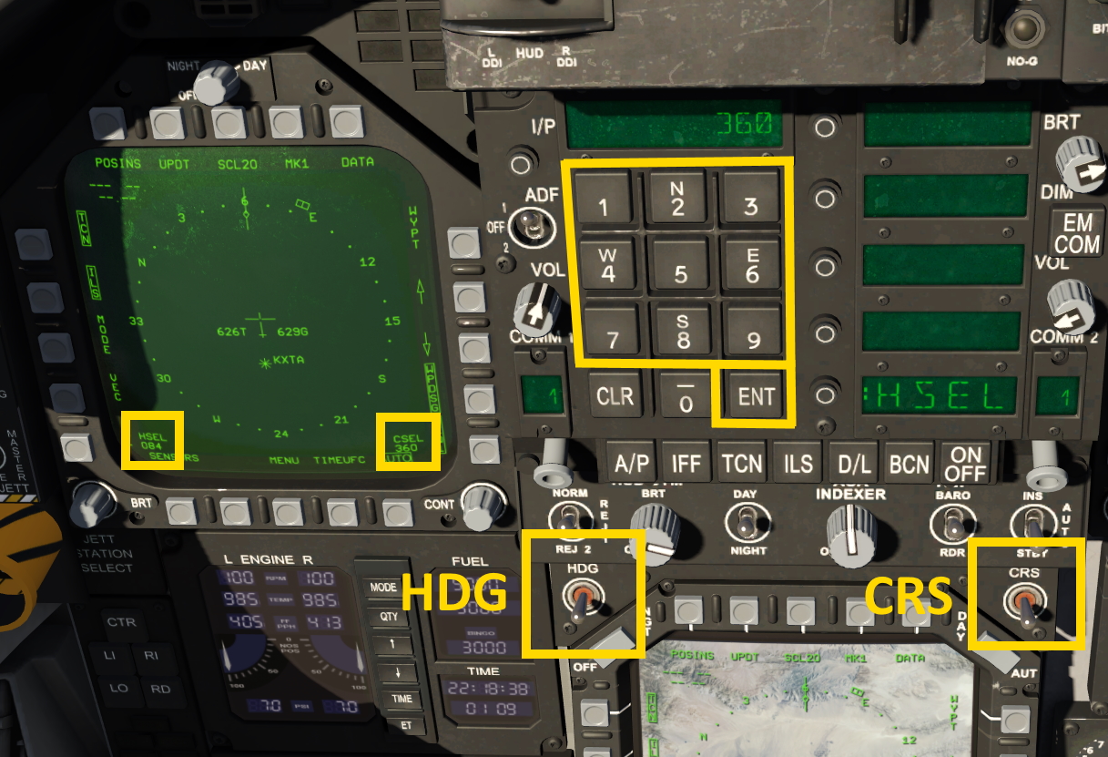
The selected heading is displayed in the lower left corner of the HSI display. The selected heading can be changed via assigned keys or with the switch labeled “HDG” in the top right corner of the lower display (MPCD). When the autopilot is in heading select mode (HSEL) you can also use the aileron trim command to change the selected heading.
The selected course is displayed in the lower right corner of the display. To change the course you need to move the switch labeled “CRS” in the top right corner of the lower display, the MPCD. You can also use the assigned keys.
Once the HDG or CRS switch have been moved the up front controller enables a direct heading or course selection via keypad. Type the heading/course (e.g. “120”) and press enter on the UFC.
Checklists
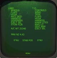
The checklist page displays a fixed text checklist for landing and takeoff. It shows the necessary items for landing:
- Wheels (down)
- Flaps (full)
- Hook (as required)
- Anti-Skid (on)
- Harness (fast)
- Dispenser (safe)
- Stow FLIR (turn radar off)
and for takeoff:
- Flight Controls (checked free and correct)
- Wing (spread and locked)
- Trim (roughly 6° nose up is ok for the current implementation)
- Flaps (half)
- Hook (up)
- Harness (fast)
- Warn lights (tested and all extinguished)
- Nose wheel steering (NWS) LO (low - do not hold pedal switch depressed for landing)
- Ejection seat armed
Flight Controls
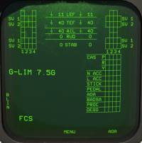
The flight control page displays the servo (SV) state for each control surface and their control deflections. The Page also shows the maximum G-limit (7.5gs positive). This could be lower if external stores are added. Arrows indicate the direction of the deflection.
- LEF - leading edge flaps
- TEF - trailing edge flaps
- AIL - aileron
- STAB - stabilizer (tailerons)
- RUD - rudder
Up Front Control (UFC)
The up front controller (UFC) is the main interface for entering values into the F18 systems. The UFC has numeric keys and several smaller display lines that are used to select options.
The main pages of the UFC menu are accessible through the buttons row beneath the keypad. These pages include: autopilot (A/P), identification friend or foe (IFF), tactical air navigation (TACAN - TCN), instrument landing system (ILS), downlink (D/L), beacon (BCN) and communication (COMM - accessed through by turning the gray knobs left and right of the buttons). The ON/OFF button is used to turn the displayed system on or off.
Entries are usually made by first selecting the page, e.g. TCN and then typing a number, confirmed with the enter key.
In Aerofly FS the UFC accepts channel numbers for the ILS, TACAN and beacons and also frequencies. Since there is no key for the dot you need to type at least four digits for a valid frequency, e.g. “1103” for 110.30 MHz.
Head Up Display (HUD)
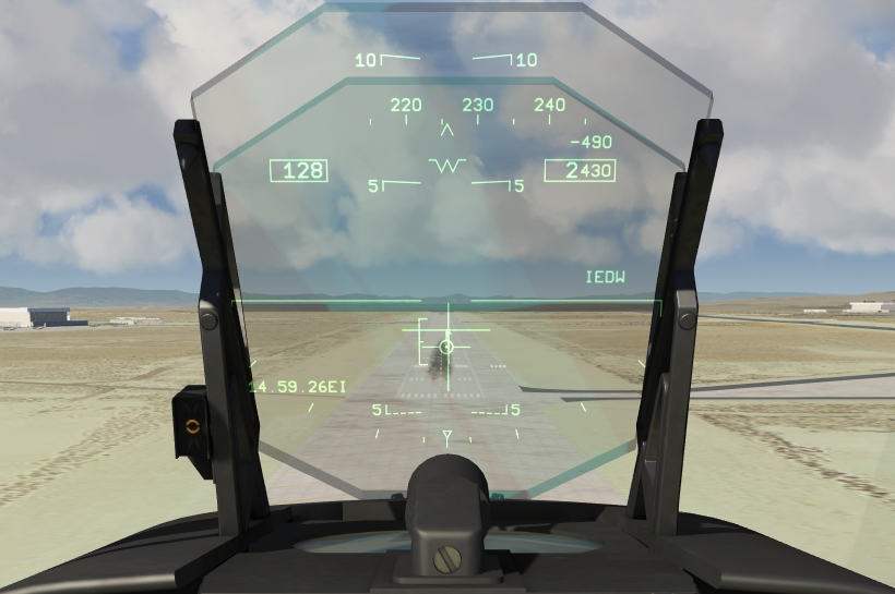
The head up display packs a lot of information onto a transparent screen in the direct line of sight of the pilot. This allows an operation of the aircraft without having to look down at the instruments.
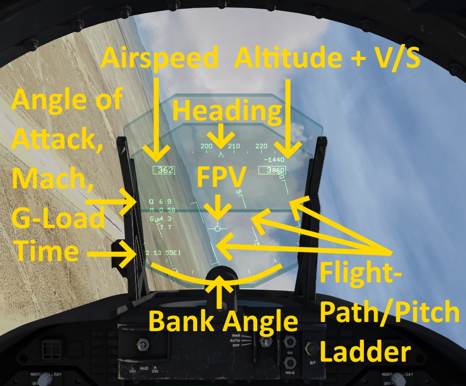
The HUD displays the airspeed, heading, altitude and vertical speed, angle of attack, mach number, current and maximum g-load, time, flight path vector, ILS and TACAN steering bars, pull up cue, arrows to the next designated target, information like DME distance, waypoint and station identifiers.
A row of switches underneath the up front controller (UFC) allows the selection of several options. The reject switch (REJ 1, REJ 2) allows the pilot to declutter the display and only display the most relevant information. The day/night switch dims the HUD for night time operations. The BARO/RDR switch allows the altimeter in the HUD to display either barometric altitude or radar altitude (above ground).
Pitch/Flight-Path Ladder
The background of the head up display is filled with the attitude indication. An artificial horizon and pitch ladder is overlayed on the actual horizon. In the F18 this pitch ladder is usually not fixed, it moves with the flight path vector (FPV) which is the true direction where the aircraft is flying to at the moment.
E-Bracket and AOA-Indexer
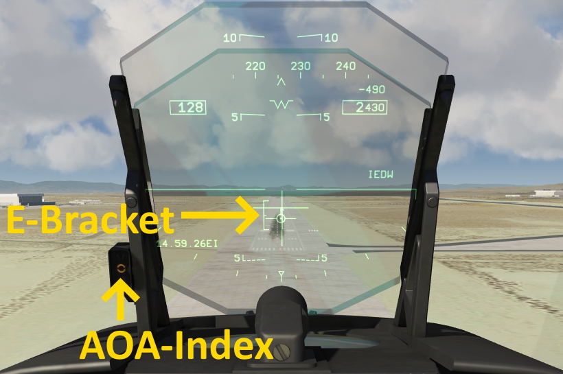
When the gear is down the angle of attack indexer (AOA-Indexer) to the left of the HUD lights up and the “E” shaped bracket appears on the HUD (next to the flight path vector). They both show the angle of attack range that should be flown during the final approach. The center tick of the E-bracket and the ring shaped light on the AOA-indexer show the ideal angle of attack for a carrier landing, where the catch hook and main landing gear have to be at the right attitude for a safe touch down.
When the flaps are selected down and the fly by wire entered the approach mode you can use the elevator trim commands to trim the aircraft and to maintain the ideal angle of attack. The aircraft will return to that angle of attack if you release the stick. Use small throttle inputs to adjust the flight path angle and avoid elevator inputs for a more stabilized approach.
Pull Up Cue
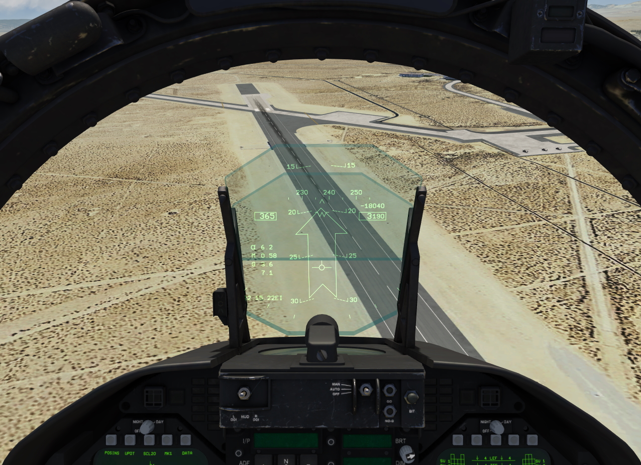
When the aircraft senses a collision thread with the terrain it displays a large pull up cue arrow that points towards the up direction. The pilot should immediately react and fly towards the tip of the arrow to avoid a collision with the terrain.
TACAN Steering Information
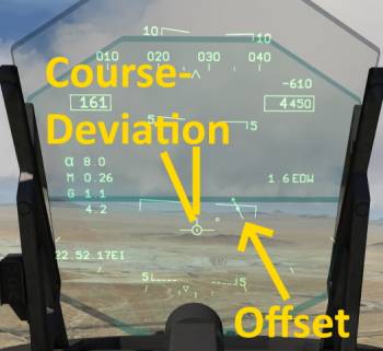
The HUD can also display tactical air navigation (TACAN) or VOR course deviations for flying towards or away from a TACAN/VOR at a set radial.
When a valid signal is received a small arrow with a deviation scale is displayed. The scale is only drawn towards one side and is removed when the deviation is small. An arrow points to the TACAN or VOR station. The angle between the arrow and the up direction shows the course deviation that is currently present.


