
This is an old revision of the document!
Table of Contents
Modelling
3D Model
The 3D model is the visible aircraft that displayed on the screen. The 3D model on the computer is a bunch of numbers that define several hundred-thousand points and their connections. Three connected points make one triangle (a tiny bit of surface) and several triangles connected to each other can approximate any shape, e.g. the shape of a certain aircraft part. This collection of triangles is called a mesh and can be imagined as a dense net that spans over the entire surface. Onto the mesh an image (texture) is overlaid to define the coloring of the surface. All meshes of the individual parts make up the '3D model' of the aircraft.
Of course not each individual point (vertex) is placed by hand. There are software programs that let the user modify primitive geometry (cube, cylinder, sphere,…) into any shape desired. These modelling tools also do a great job of flattening/stretching the 3D surface of triangles into a flat surface so that it becomes easy to assign parts of an image (texture) to a part of the model (uv-mapping).
Example Aircraft - Robin DR-400
In the SDK we have included an entire aircraft project, the Robin DR-400, including its 3D model and textures. By following the few steps of the aircraft tutorial the necessary development programs will be installed and at the end of the tutorial the DR-400 will be installed as an additional aircraft in the simulator.
Please note that the 3D model of the Robin DR-400 provided is copyrighted and may not be used for any other purpose then demonstrating how to create aircraft for the Aerofly FS 2.
Supported Modelling tools
Currently (30th January 2017) the Aerofly FS 2 Software Development Kit (SDK) supports 3D Studio Max 2010 or higher, Maxon Cinema 4D version 17 and AutoCAD (AC3D) 3D version 8.
Bringing the Model into the Aerofly FS 2
After installing the SDK we will now go through the steps of converting a custom made 3D model from 3Ds Max into the Aerofly FS 2 Flight Simulator.
Preparing the 3D Model
To achieve an error free export some preparation is needed to be done first. For the DR400 example aircraft all these steps have already been completed so that this plane can be used as a reference.
Single 3D Model
Aerofly FS 2 works with just one 3D for an entire aircraft; there is no need to provide an external and internal model separately. The Aerofly FS 2 engine is optimized to draw only those objects that are in the view of the camera.
Generic Modeling Units
The units of the aircraft model should be set to 'Generic Units'.
Alignment and coordinate system
The aircraft should be aligned to the x-axis as the forward flight direction, the positive y-axis towards the left and the positive z-axis pointing upwards. The origin of the model coordinate system should be placed close to the center of gravity.
Animated objects should have their axis and rotation pivots set to a plausible location. Hinged objects should have their local origin in their hinge location. The pivots and axes set in 3D Studio Max will be exported to the log files which will be used later on to animate the objects in the graphics section of the .tmd file.
Animated objects should be positioned in the following neutral positions before export:
- control surfaces neutral, flaps up
- gear down and compressed as if the aircraft would stay on the ground
- gear doors closed to assure perfect alignment when the gear is retracted in flight
- cabin doors and windows closed
- knobs and switches that are not planned to be animated should be in an in-flight position
- switches and knobs that will be animated are best exported in their off state
- instrument needles point to zero or neutral depending on the instrument
- magnetic compass points towards 090 degrees (East). This is needed because the x-axis of the global coordinate system of the Aerofly FS 2 points towards the East as well.
Individual objects
All animated objects like the control surfaces (rudder, aileron, elevator) and trim rudders, switches and knobs, gear parts and so on have to be individual objects in the 3D model so that they can be animated independently from each other. The Aerofly FS 2 rendering engine is optimized to merge objects in the same GeometryList when the aircraft is loaded, so there is no real benefit combining objects. Experience has shown that development time can be reduced if all switches and knobs are available as individual objects right away and the model doesn't need to be changed every time a developer decides to animate a certain switch.
Display screens have to be separate objects so you can set the display brightness independently of the background lighting later.
Object naming conventions
3D objects will be referenced by their name for display and animations, so it is essential that each object has a unique name. Objects should be named logically, and the name must not contain spaces or special characters (it is recommended to use A-Z, a-z, 0-9 only). While the object names have no meaning to the simulation, it is easier for everyone working on the project to use standardized names. We use the 'UpperCamelCase' convention, i.e. we capitalize the first letter of each word to get short but readable object names.
Advisable names are e.g.:
Fuselage, LeftWing, LeftAileron, LeftFlapInner, LeftSlat1, LeftSpoiler1, LeftSpoiler1LinkUpper, LeftStabilizer, LeftElevator, VerticalStabilizer, Rudder, LeftGearUpper, LeftGearLower, LeftFrontWheel, LeftPropeller, LeftBlade1, LeftBlade2, VirtualCockpitStatic, SwitchBatteryMaster, MCDUPushButtonA, CanopyFrame, CanopyGlass, COM1FrequencyKnobSmall, NAV1FrequencySwap, LeftEngineFan, LeftEngineExhaust, LeftEngineRevererFlap0, PrimaryFlightDisplayPilot, NavigationDisplayCopilot,…
Materials
Materials are defined by the set of textures they use and by tags or hints that describe the intended usage. A simple material just needs a diffuse texture, but Aerofly FS 2 also supports ambient, specular, bump/normal, reflection, (self-)luminance and illumination textures to define the material parameters at each texel. Use the 3D software's standard material and the following texture slots:
- Diffuse: diffuse color. An optional grayscale '_alpha' texture can be provided to add transparency information (black is fully transparent).
- Ambient: ambient color. This is a separate grayscale RGB map.
- Bump: bump map if texture name ends with '_bump', normal map if name ends with '_normal'. The bump maps of a model will be converted to normal maps by the aircraft converter.
- Specular: specular highlight color and strength. Color and strength are given by RGB values of the texture, specular highlight width is controlled by the alpha channel
- Reflection: strength of sharp reflection. Red color channel controls the strength of the environment reflection. Do not use the green and blue channels as they are reserved for other purposes.
- Self-Illumination: color luminance map.
- Filter Color: illumination. RGB channels encode the illumination strength/lightmap for the interaction of the diffuse color with three independent light sources. (This slot is used in 3D Studio Max only. In most cases, we don't assign these textures explicitly but use the suffix '_illumination' and let the converter add the texture to the material.
We use the suffixes '_color', '_ambient', '_bump', … to distinguish the different textures that make up one material. These suffixes are not required but allow the aircraft converter to automatically add textures to a material if they have the same base name, and the 3D modeling software doesn't support a particular texture slot.
Textures
All textures must be square power-of-two images with a pixel depth of 24-bit RGB .bmp, 24/32-bit .png or .tif files. Bump maps can be 16-bit grayscale textures. There is no support for .psd files in the converter, the different layers for diffuse, ambient, .. have to be exported to the intermediate folder first. You can keep a .psd file assigned to a texture slot in the 3D software if it has the name as the bitmap file except for the suffix.
It is recommended to create all textures at a resolution of 4096×4096 or even 8192×8192 pixels, and use the appropriate converter setting to reduce the actual size used in the simulator. The smallest size recommended is 32×32 pixels, the maximum supported texture resolution by the engine is currently 4096x4096px. The total compressed texture amount should be in the range of 150 MB to ensure compatibility with all platforms. The final texture resolution can be set in the 'model.tmc' file.
Refresh Texture assignments
If necessary, refresh the texture assignments in the 3D modeling software to use the exported textures in the intermediate folder. Again, you can keep a .psd file assigned to a texture slot in the 3D software if it has the name as the bitmap file except for the suffix. The converter ignores the texture suffix, so you can change from .bmp to .tif without changing or exporting the 3D model again.
Material Tags or Hints
Each material can define tags or shader hints to support the selection of the best shader when the aircraft is loaded. Shader hints can be combined to describe the material properties as precise as possible. Currently, the following shader hints are supported:
| exterior | everything that is not in the cockpit/cabin, outer faces of windows and canopy |
| interior | everything that is in the cockpit and cabin, inside of windows and canopy |
| default | |
| standard | |
| glass | |
| canopy | |
| window | |
| instrument | |
| darken |
The hint can be added to a material in 3D Studio Max as follows:
- Select an object that uses the selected material
- Open 'Animations' → 'Parameter Editor'
- Select 'Add to Type' → 'Selected Object's Material'
- Select 'Parameter Type' → 'String' and
'UI Type' → 'EditText' - Enter 'shader' in the 'Name' textbox
- Click the 'Add' button
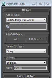

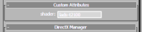
- The material now has a 'Custom Attribute' where you can enter the desired tags.

Exporting from 3D Studio Max
If you haven't done this yet, install the export plugin as described above. Load the aircraft in 3D Studio Max and select 'Export' → 'Export' and select the aircraft's intermediate folder. Select 'IPACS TGI Exporter (*.TGI)' and save to 'xxxx.tgi'. Select the output option 'Aircraft model' in the exporter menu and set the scale factor to
- 10 if the one generic unit in 3D Studio Max corresponds to 1 mm
- 100 if the one generic unit in 3D Studio Max corresponds to 1 cm
- 10000 if the one generic unit in 3D Studio Max corresponds to 1 m

After all parameters have been entered a click on the button 'Export' will launch the export process. The export summary will notify the user about any errors in the export process and will summarize the total polygon and vertex count and other statistics.

Converting
When you have collected all required files for an aircraft in the intermediate folder, run the aircraft converter: right click on the 'xxxx' intermediate folder and choose Aerofly FS 2 Aircraft Converter from the context menu. This opens up the converter window and the aircraft's internal name xxxx should be displayed. Start the conversion. If run for the first time, the converter will convert and compress all textures and render the previews. This might take some time depending on your hardware.
The next time you convert the aircraft, the converter will only converter will process only those textures that have been changed. You can always force the conversion of a texture or preview by deleting the generated file.
If you want to change the output folder, you can set this in the 'config.tmc' file located in your 'Documents/Aerofly FS 2 Aircraft Converter' folder. Change the entry 'DesktopFolder' to match your folder.
The same folder contains the converter's log file 'tm_aircraft_converter.log', which sometimes is helpful for troubleshooting, as well as the 'report.txt' in the aircraft's intermediate folder.