IPACS

A320 MCDU Programming

In the Aerofly FS Flight Simulator the A320 Multifunction-Control-Display-Unit (MCDU) is simulated realistically and in great detail. This device can be used to create a new flight plan, tune navigation radios, set and adjust the performance of the aircraft and a whole lot more.

The MCDU has many pages of which a lot are simulated. You can access the most relevant pages directly by clicking one of the page buttons under the MCDU screen. Some sub-pages can then be accessed through clicking line select keys, e.g. then an arrow on the screen is pointing at the line select key.

Data entry is accomplished by typing a value into the MCDU scratchpad first. Then the value can be inserted into a field on the displayed MCDU page with the line select key next to it.

We’re now demonstrating the necessary steps to create a flight plan using the MCDU in the A320.

Note - If you select the “before engine start”, “ready for taxi”, takeoff or landing state these steps will all be taken care of for you. And you can always go back to the navigation menu to change the navigation route, too.

MCDU Flight Preparations

Data

We’re now entering a full flight from one airport to another using the Multifunction-Control-Display-Unit (MCDU). If you already set up a flight plan with the navigation menu you can skip a lot of the following steps. We’ve highlighted the necessary steps in bold text.

  • Select the MCDU MENU page if not already displayed by pressing the MCDU MENU button on the MCDU
  • Select FMGC by pressing the line select 1L
  • The aircraft status page is displayed

In the real aircraft we’d now have to check if the navigation database is still up to date.

Initialization A

Let’s create a new flight plan

Note - You can cheat and get enter useful values by double clicking the line select key next to empty field.

  • Press the INIT button to display the initialization page
  • Enter the airport ICAO codes for your route. We’re at Frankfurt and want to fly to London Heathrow so we insert “EDDF/EGLL”
  • Enter an alternate airport identifier if we need to divert, e.g. “EGKK”
  • Enter the flight number if this is a scheduled flight
  • Enter a cost index of 20 or as desired. A higher number increases the cruise speed which reduces the flight time at the cost of higher fuel burn. The minimal fuel burn is achieved with a cost index of zero
  • Enter a cruise altitude for the flight, e.g. 35000 for FL350

Flight Plan Departure

Now we’re entering our departure runway and standard instrument departure (SID). This enables the autopilot to climb to our cruising altitude in a safe manner.

  • Click the F-PLN button on the MCDU
  • Push the left line select button next to your departure airport in the first row
  • On the LAT REV page push the upper left DEPARTURE option
  • Select the departure runway from the list. You can scroll the list using the up and down arrow buttons on the MCDU. Pushing the up button slides the page up and allows you to scroll down to the other runways. We’re using EDDF runway 25C here
  • After you selected a runway you can select a standard instrument departure (SID) by pressing the left line select keys next to it. We’re using the RID3Q departure
  • Select the TMPY INSERT* option in the lower right to accept the changes to the flight plan

Flight Plan Arrival

After inserting the departure the flight plan should be displayed again (otherwise push the F-PLN button again). Let’s insert an arrival for the destination.

  • Push the F-PLN button
  • Now select the line select 6L next to your destination airport
  • Select arrival in the top right and then pick an approach from the list. You can scroll with the MCDU arrow keys. We’re using the ILS27L at EGLL
  • After selection of the approach the list of standard terminal arrival routes (STARs) is displayed, select the desired one from the list. We’re using the STAR “BIG1F ” for our flight
  • Select TMPY INSERT*

Delete Discontinuities

Note - With the latest Aerofly FS 2023 and Aerofly FS 4 you now have a route discontinuity between the departure and arrival because we have not told the aircraft how to connect the two. This is how the real aircraft behaves.

  • Push the F-PLN button
  • Step through the individual waypoints on your route by pressing the MCDU up and down arrow buttons.
  • Press the CLR button on the keypad so that the scratchpad shows CLR.
  • Then press the left line select key next to the disco entry in the list to delete the F-PLN-DISCONTINUITY line.
  • Repeat for all discos

Verify Route

  • Select the PLAN option on the navigation display (ND)
  • Use the RANGE knob as needed to change the display range.
  • Push the CSTR button to display the altitude and speed constraints on your navigation display (ND)

Now you can step through the individual waypoints on your route to check each one

  • On the MCDU press F-PLN
  • Press the MCDU up and down arrow buttons to change the selected waypoint

Radio Navigation

On the radio navigation page you can manually tune the frequency of ground based navigation aids or let the flight management system tune these automatically for you (FMS auto-tuning).

You can either enter a frequency or a station identifier which sets the frequency from database.

  • Set the navigation display to the ROSE or ARC mode
  • Push the VOR.D button to display VORs and DMEs on the navigation display or push the NDB button to display non directional beacon stations
  • Type the station identifier into the scratchpad and insert it into a field with the line select key next to it
  • We’re manually tuning the Ried VOR (RID) for the VOR1 receiver which is part of our departure route
  • Set the ADF/VOR 1 switch to the VOR 1 position to display the bearing needle on the ND

The MCDU now displays the VOR1 identifier field in large letters which indicates a manual selection. Automatically tuned stations are always kept in small text size. To resume automatic tuning

  • Push the CLR button to insert CLR into the scratchpad
  • Push the line select key next to the field where you want to remove the manually tuned identifier or frequency

Initialization B - Weight and Balance

Now we’ve entered our full flight plan and can perform the fuel calculations.

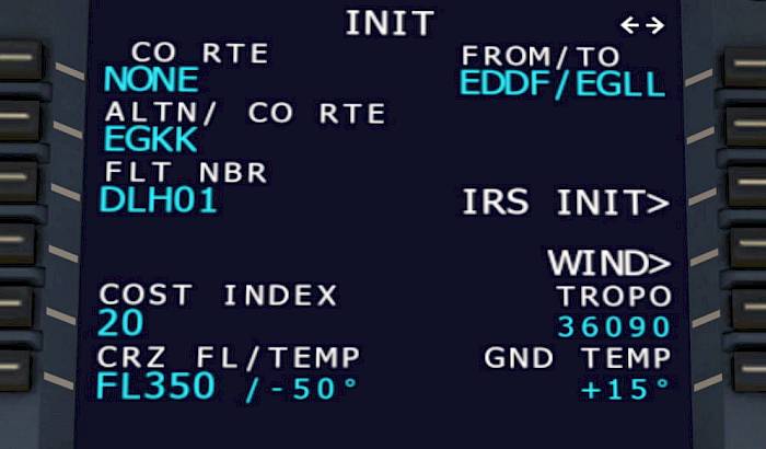
  • Push the INIT button to display the INIT A page again
  • Go to the INIT B page by pressing the arrow left/right buttons on the MCDU
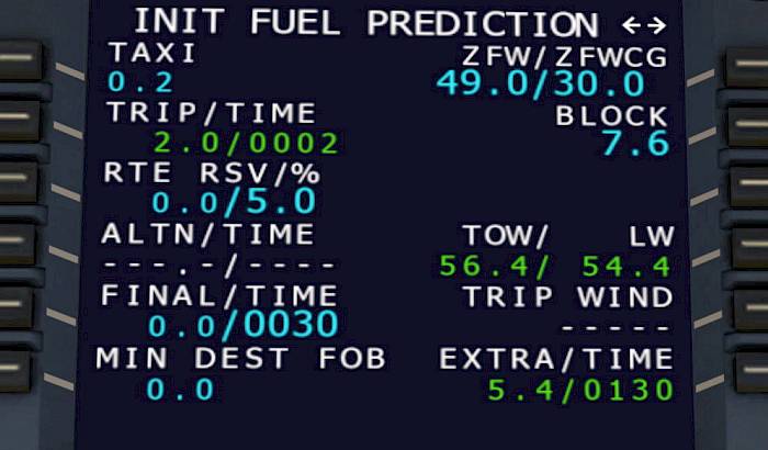
  • Enter the zero fuel mass in metric tons and zero fuel center of gravity (ZFW/ZFWCG), e.g. “49/30”

If you have a route planned and haven’t done a fuel planning otherwise you can now select the FUEL PLANNING option to compute suggested fuel figures.

  • Push the FUEL PLANNING option to compute the different weights for the flight

If we don’t want to use the automatic option or when we want to change it we can do that:

  • Manually set the block fuel mass, e.g. the current fuel on board, for us that’s “7.5’ metric tons
  • Enter the taxi fuel if you expect a longer than usual taxi
  • Change the reserves as required

On the right hand side you can now see your expected takeoff mass (TOW) and landing mass (LW) in metric tons. In the lower right you can see the extra fuel and time, that is fuel and endurance that is remaining after you’ve flown to your destination and then to your alternate airport and performed a holding for 30 minutes.

Performance

In the real world your company can send you the performance figures for your flight based on your flight number and flight plan origin/destination.

  • Press the PERF button to display the performance pages
  • If UPLINK TO DATA is displayed in the lower left you can click on the line select key next to it.
  • Once received you can click on CONFIRM TO DATA* in the lower right of the page

You can also manually fill in the performance values

  • Enter the V1 decision speed (e.g. 135)
  • Enter the VR rotation speed (e.g. 140)
  • Enter the V2 initial climb speed (e.g. 142)
  • Check the airport transition altitude
  • Check the thrust reduction and acceleration altitudes as well as the engine out acceleration altitude
  • Enter the takeoff flap and trimmable horizontal stabilizer angle, e.g. “1/UP0.0” or “2/DN0.2”
  • Enter a flexible takeoff temperature if the conditions allow
  • On the next page you can enter a PRESELected airspeed for the climb if the departure requires a tight turn, this is optional

When you change your departure runway the MCDU shows a CHECK TAKE OFF DATA message.

  • Press the PERF button
  • Review the entered values and when they are acceptable: Press CONFIRM TO DATA* in the lower right of the page
  • You may have to re-enter the takeoff flaps and trim

(Optional) Waypoint Fix Info

Using the MCDU we can draw guidance lines onto the navigation display. These help us judge distances or inbound radials towards navigation fixes.

  • Push the F-PLN button
  • Make sure your scratchpad is empty (use CLR key if necessary to remove all text)
  • Push the line select key on the top left (1L)
  • Select FIX INFO on the top right
  • Type a waypoint, VOR, NDB, airport or runway identifier into the scratchpad (e.g. EDDF25C)
  • Insert the identifier into the REF FIX field
  • Set a radial and radius
  • Change the range and mode on the navigation display to see the cyan dashed lines

To delete the fix

  • Open the fix info page as shown before
  • Push the CLR button to insert a CLR command into the scratchpad
  • Press the line select key next to the fix identifier (where it was entered) to remove it

Tutorials