 English
 Deutsch
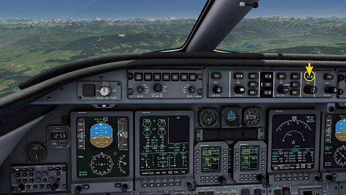
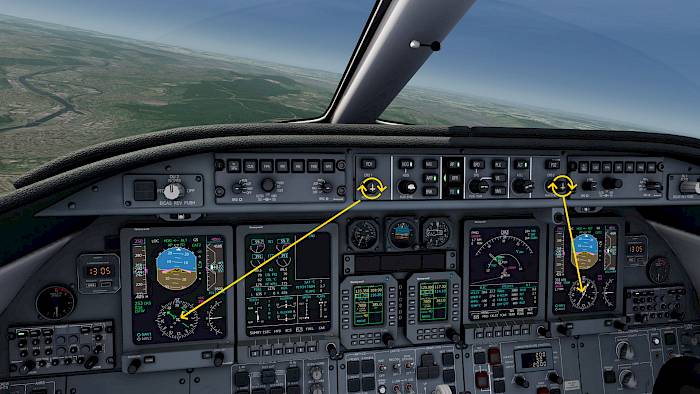
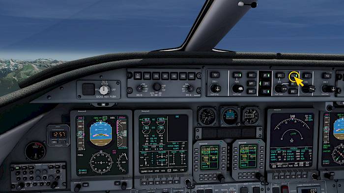
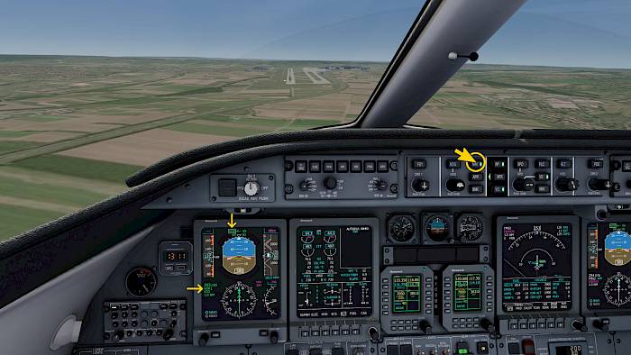
Flight Guidance Control Panel (FGCP)
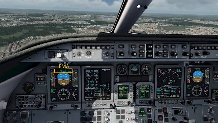
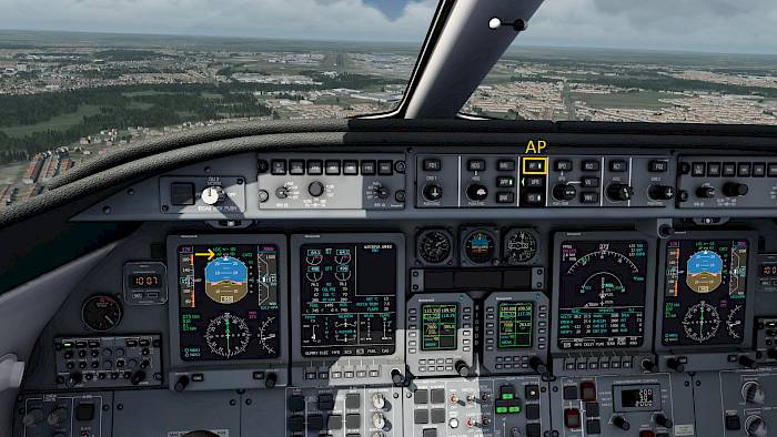
The Flight Guidance Control Panel (FGCP) or Flight Guidance Controller (FGC) as it’s called in some aircraft is the autopilot panel with buttons and knobs that controls the autopilot system.
Familiarize yourself with the panel layout by reading the button and knob labels and texts.
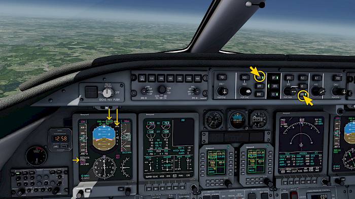
In the Learjet 45 the FGC is split into several columns:
- FD1 and CRS1
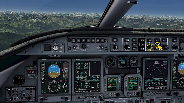
- Lateral Navigation
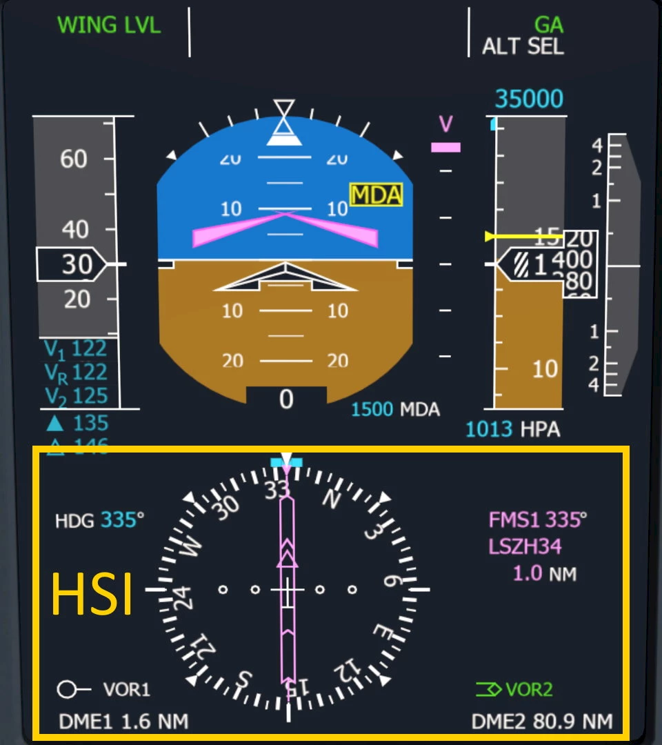
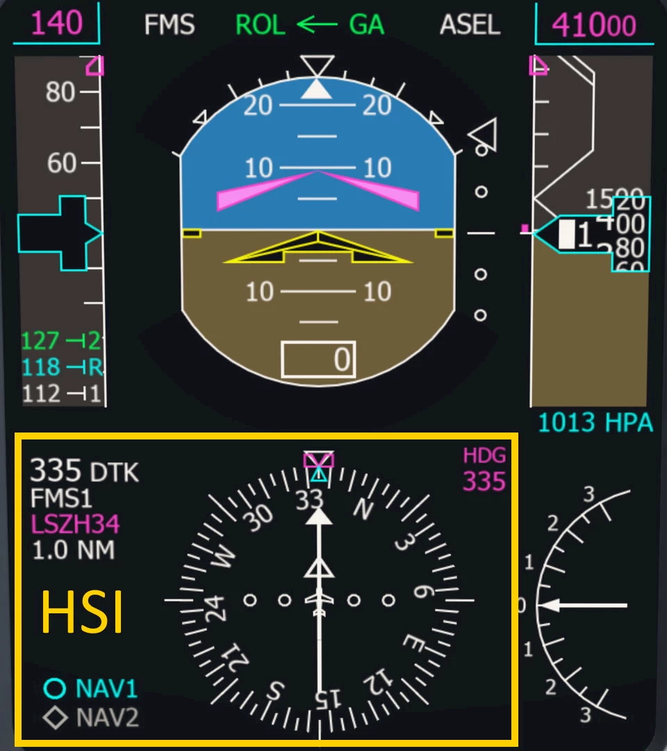
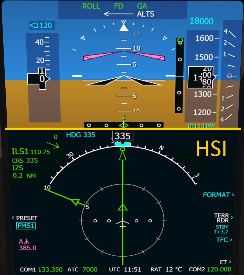
- Autopilot, HSI Side, Yaw Damper
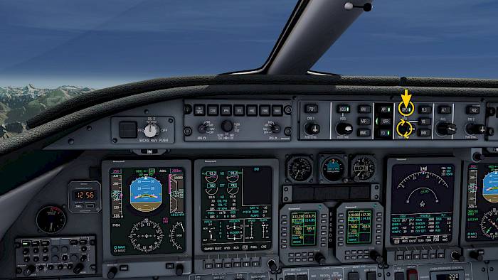
- Vertical Navigation
- Altitude
- FD2 and CRS2
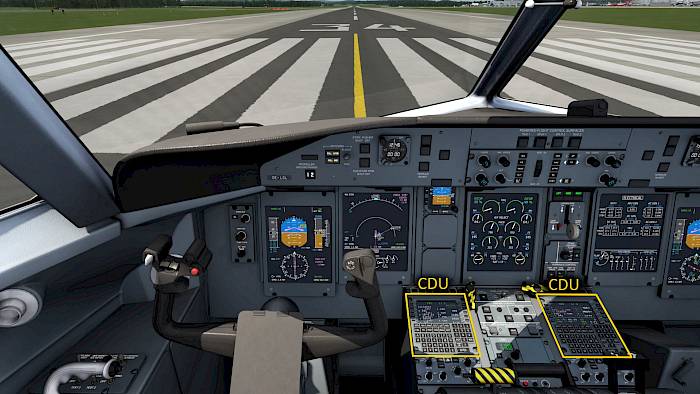
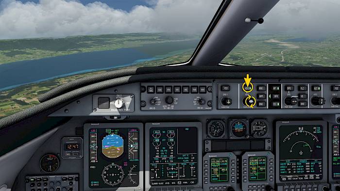
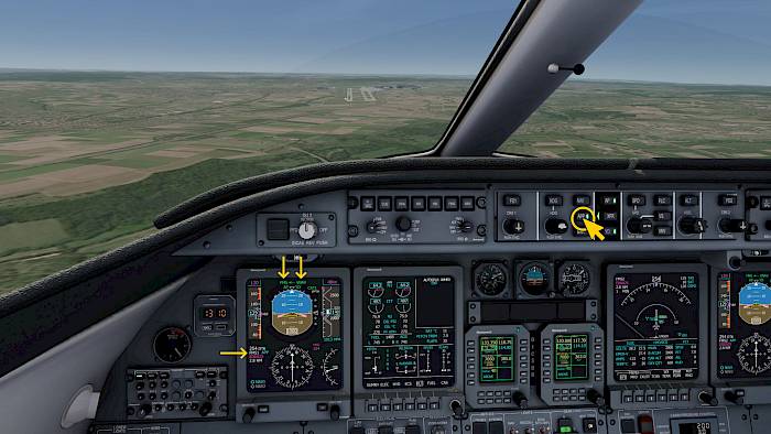
The King Air and CRJ-900 are similar but the columns are rearranged compared to the Learjet. They also feature a vertical wheel for the pitch attitude and vertical speed adjustment.
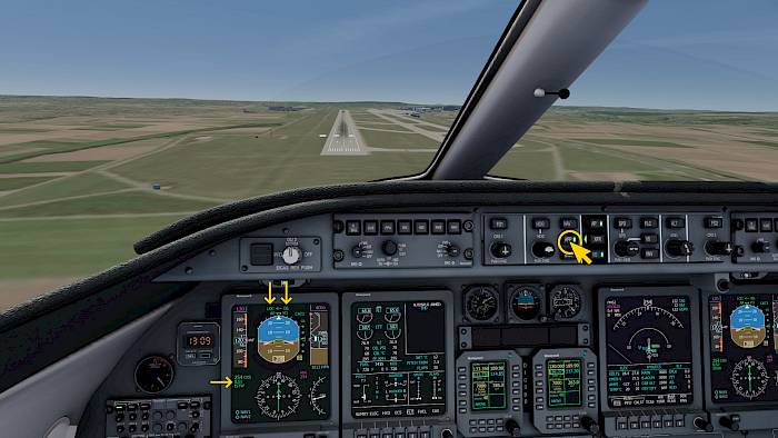
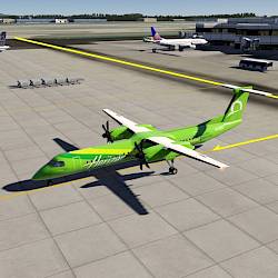
The Q400 arrangement is different with knobs for the CRS, HDG, NAV Source and Altitude moved to the side, the vertical wheel in the center and vertical mode buttons on the left of the vertical wheel and lateral mode buttons on the right side.