IPACS

UH-60 Black Hawk Flight Tutorial

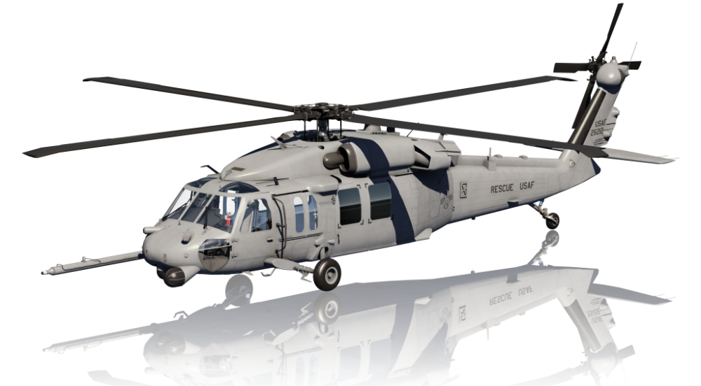
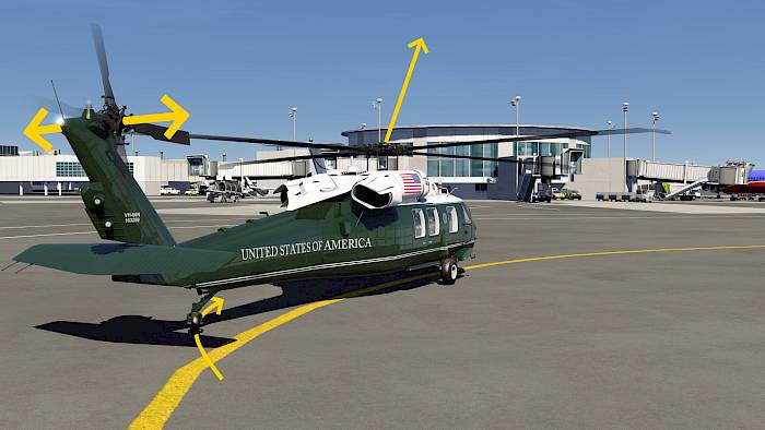
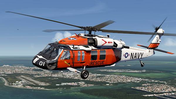
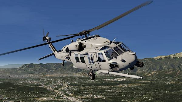
The Sikorsky UH-60 Black Hawk is a twin-turboshaft medium-lift utility helicopter which is simulated in great detail in Aerofly FS. It is used as a military helicopter, medical evacuation (MedEvac) and fire fighting. Civilian versions are designated as Sikorsky S-70.

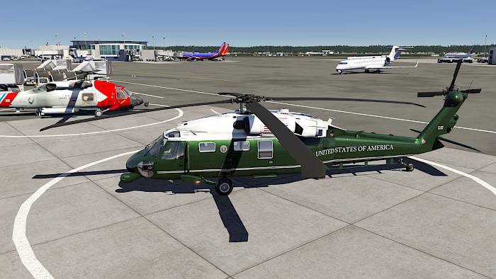
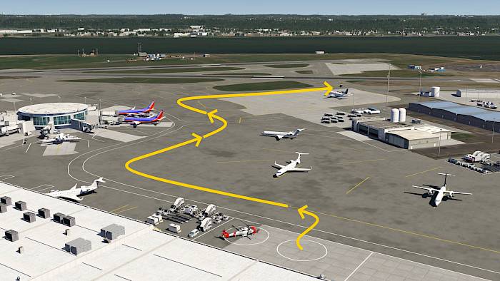
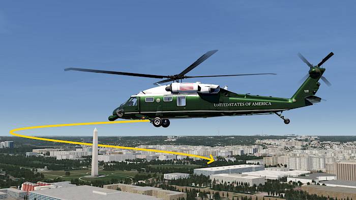
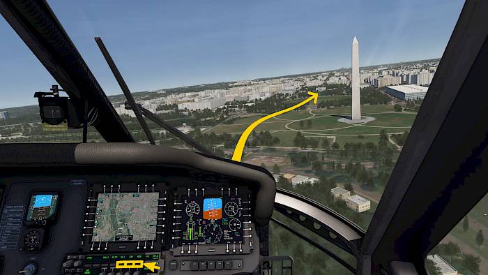
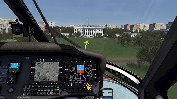
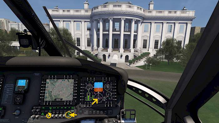
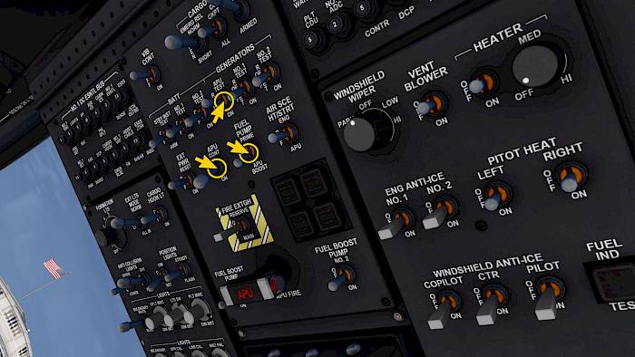
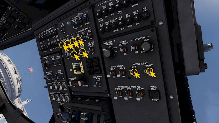
In this tutorial we’ll show you how to start the engines from a “cold and dark” preset, with all engines cold and electrical systems off and cockpit dark, just like for the first flight of the day. To start this tutorial please click on a parking position or helipad in the location menu and then select the cold and dark option. We’re starting our tutorial at the Washington Ronald Regan Airport in the south west apron. From the Ronald Regan Airport we’re going to fly north east before heading back west to the White House to drop off the President of the United States of America. This scenic route will take over the Capitol and Washington Monument.

Recommended Control Assignments

To use the UH-60 to it’s full potential we recommend using a joystick and rudder pedals as well as a throttle quadrant such as the Thrustmaster TCA Quadrant (with Add-Ons).

Assign on the joystick:

  • Elevator and aileron trim (e.g. to your joystick hat switch), these are very helpful when using the autopilot
  • Autopilot disengage
  • (Optional) Autopilot master (default key is ‘A’)
  • (Optional) Autopilot go-around

Assign on the throttle quadrant

  • Throttle levers to helicopter throttle 1 & 2
  • Speed brake lever to helicopter rotor brake
  • Engine Masters 1 & 2 in twin jet
  • Engine Starter 1 & 2 in twin jet
  • Engine Ignition in twin jet

Note: If you have the TCA Quadrant most of these are already assigned per default.

Mission Planning

Starting Position

We’ve set up a simple route which takes us north east from the Ronald Regan Washington National Airport around the District of Columbia in an anti-clockwise fashion. This route is automatically loaded in the UH-60 and we can use it for the autopilot later on. This is optional and you don’t need to copy this exact routing.

Check the Area Clear

  • In the location menu select the start position on the ground
  • Select the cold and dark option on the right hand side
  • Start the simulation

Check that the area around you is clear. The UH-60 is quite a large helicopter and needs a lot of space. If there are objects nearby you may need to select a different start position in the location menu.

Preflight

Cold And Dark

Welcome to the UH-60 Cockpit. Because we have selected the cold-and-dark preset all our Multi Function Displays (MFDs) and Control Display Units (CDUs) are currently off.

  • Make sure that your collective lever is down
  • Center your cyclic stick

Batteries On, APU Start

  1. Select the battery switch #1 to on
  2. Set battery #2 on
  3. Arm the standby instrument battery (STBY INST)
  4. Set the FUEL PUMP switch to APU BOOST
  5. Start the Auxiliary Power Unit (APU) by setting the APU CONT switch to ON
  6. Wait for the APU ON light
  7. Set on the APU GEN switch

MFDs On

With the APU generator on we now have a AC electrical power source and can turn on the MFDs.

  • Set all four MFD switches to ON
  • Rotate the IGNITION switch to ON

Pedestal

In the pedestal

  • Set on the SAS 1, SAS 2, TRIM and FPS switches
  • Verify that SAS/BOOST and the stabilator AUTO CONTROL switches are ON
  • Check that CPTR 1 and 2 flight control computer reset switches are off
  • Set the Embedded GPS Inertial Navigation System - EGI 1 and 2 switches to ON
  • Check that the parking brake lever is pulled
  • Check that the tail wheel is locked
  • On the ARC-231 backup COM panel set the mode selector to NORM

Check EICAS

On the EICAS (Engine Indicating and Caution Advisory System) display check that the right hand column is empty.

Note if you are seeing message for the left and right pitot tube you can remove them by setting the PITOT HEAT LEFT and RIGHT switches on in the right hand side of the overhead panel.

On the left hand side verify

  • APU ON and APU GEN ON
  • PARKING BRAKE ON

CDU Preflight

Transponder

Our IFF (Identification Friend or Foe) is currently on standby. In non-military aircraft this usually called the transponder. In military aircraft such as the UH-60, F-18, F-15 and others the IFF has more functionality and pilots have more control over signal emission to avoid being seen by enemies.

  • On the Control Display Unit (CDU) select the transponder control page by pressing the XPD page button
  • Push the third line select key on the right hand side to set the transponder mode (XPDR MODE) from STBY to NORM

Communication

Using the Control Display Unit (CDU) we can also set the communication frequencies.

  • Push the COM button to open the communication summery (COM - SUM) page
  • Use the third line select key on the left to highlight the VHF frequency. Push multiple times to move the cursor between the channel number and frequency field, select the frequency field
  • The scratchpad now shows an empty template [_.]
  • Type in the desired frequency, in our case “119.1”
  • Push the ENT key to enter the scratchpad value into the selected field

Navigation

On the radio navigation (RADIO NAV) page we can adjust the frequencies for our VOR, ADF and TACAN (TACtical Air-Navigation) receivers.

  • Push the NAV key to access the RADIO NAV page
  • Select the VOR frequency field by pushing the line select key 1 left multiple times until the cursor is on the frequency.
  • Type in the frequency, e.g. “110.0”
  • Press the ENT button to insert the value

Engine Start

Starting Engine

We are now ready to start our engines

  • Verify the ignition switch in the front panel is set to ON
  • Verify the APU is running (APU ON) and the bleed air source (AIR SCE HT/STRT) is set to APU
  • Verify the rotor brake is off
  • Move both fuel selectors for engine 1 and 2 forward to XFD (cross feed) for the first engine start of the day or DIR (direct) for any subsequent starts
  • Push the engine starter button on the POWER CONT lever to initiate the engine motoring
  • On the EICAS we can now see an ENG 2 STARTER ON message appear
  • Move the POWER CONT lever from OFF to IDLE. If you have the twin jet engine masters assigned you can also use these to set these levers to IDLE.

Monitor Engine Start

We observe the engine start.

  • Check that the rotor starts spinning
  • Check the peak start Turbine Gas Temperature (TGT) stays within limits

After the engine has sped up to about 58% the starter should automatically have disengaged.

  • Verify that ENG 2 STARTER ON is no longer visible on the EICAS

Then repeat the start process for the other engine. Push the starter button, introduce fuel and let it stabilize.

Slowly Increase Rotor Speed to 100%

When both engines have been started we can increase the rotor speed for takeoff.

  • Slowly move the POWER CONT levers forward

The engines will spool up and rotor speed increases.

Power Control Levers to Fly

As you are increasing the POWER CONT levers you can monitor the rotor speed (NR) on the Primary Flight Display (PFD) power pod or on the EICAS in the center.

When the rotor speed (NR) governor has taken over the rotor speed no longer rises.

  • Move the POWER CONT levers all the way forward to the FLY position

After Start - APU off

We now have both engine generators to supply electrical AC power to the aircraft. Now turn off the APU.

  1. Turn off the APU generator
  2. Turn off the AIR SCE HT/STRT switch
  3. Turn off the APU CONT switch
  4. Set the FUEL PUMP switch to off

Taxi

Unlock Tailwheel

We’re now ready for taxi and have received clearance to taxi to the active runway. For ground taxi we can unlock the tail wheel of the UH-60. The tail wheel is then fully free castering (much like on a shopping cart) and makes it possible to turn around on the spot.

  • Feed on pedals, ready to counter any undesired yawing motion
  • Hold the wheel brakes and release the parking brake
  • Push the LOCK/UNLK switch to set the tail wheel to unlocked

Taxi with Collective, Cyclic and Tailrotor

  • Release brakes
  • Use tail rotor inputs to steer and
  • Collective and cyclic to taxi

To control the direction during taxi we use tail rotor inputs with the pedals. Even if the helicopter is stopped we can turn around (as long as parking brake and wheel brakes are released).

To increase forward speed we increase the collective slightly and hold the cyclic stick forward a little bit as well.

Taxi to the active runway

We’re now taxiing to the runway for departure. Often helicopters receive takeoff clearance from a taxiway as well but we’ll assume we have to wait for our turn at the runway holding position.

  • Taxi to the runway at less than 15 knots. Take turns slowly because the tail wheel is still unlocked and we don’t want to tip over.

To slow down we gently apply the wheel brakes or use very small aft cyclic input with small collective inputs.

Takeoff

Before Takeoff Checks

Once we are aligned with the runway we taxi straight for a short distance to straighten our tailwheel. The tail wheel light should come on when the wheel is centered.

  • Gently apply pedal inputs until the TAIL WHEEL light is green
  • Push the tail wheel UNLK switch and verify the wheel is locked with a green LOCK indication on the switch.

Now we check the EICAS for any remaining memory items (white MEMOs)

  • WOW (Weight on Wheel) is expected
  • landing and search light can be on
  • Parking brake should be off - no indication
  • IFF should be on - no IFF STDBY indication (XPD page on CDU shows transponder mode NORM)
  • Check rotor speed (NR) is at 100%

Autopilot Takeoff

We are using the autopilot for takeoff. (This may not be allowed in the real world). The autopilot can be controlled with the Flight Director Display Control Panel (FD/DCP) found just below the inboard MFD screens.

  • Push the button labeled GO ARND
  • Check that the Go Around (GA) modes activate on the Primary Flight Display (PFD)
  • A magenta collective cue appears on the PFD which shows that the autopilot is raising the collective automatically.

The autopilot now pitches forward and slowly increases speed to 70kt whilst increasing vertical speed to about 750FPM.

  • You can use small lateral cyclic inputs and tail rotor inputs to control the lateral direction.
  • Use small cyclic inputs to override the autopilot commands if you need to

Autopilot Altitude Preselect

Reaching 70kt and 750FPM after takeoff the autopilot engages the Indicated Air-Speed (IAS) hold mode and Vertical Speed (VS) hold mode. This can be seen on the Primary Flight Display (PFD) as a mode change to IAS and VS.

  • Change the target airspeed by rotating the IAS knob (e.g. 120kt) or by using assigned pitch trim commands
  • Adjust the target vertical speed with the collective trim switch
  • Rotate the ALTP knob and set e.g. 1000ft or 1500ft as your desired altitude taget
  • Push the ALTP button to arm the altitude preselect capture function, shown as white ALTP on the PFD

When you reach your the ALTP target the autopilot automatically captures and maintains that altitude.

Tactical Map

The UH-60 has several different displays that can be displayed manually by the pilot. Each MFD can show the Primary Flight Display (PFD), the Navigation Display (ND), Engine Indication and Caution Advisory System (EICAS), Tactical Map (TAC) and Joint Variable Messaging Format (JVMF) datalink communication pages.

  • On the right inner MFD push the lower bezel select button labeled “TAC”
  • You can set the left inner MFD to TAC as well or select ND
  • Push the bezel button on the left edge of the device to adjust the map zoom

Autopilot LNAV

If you have a route programmed in the Aerofly FS navigation menu you can now use the autopilot to follow it:

  • Rotate the NAV SRC knob to set FMS as the source on the autopilot (which may already be the case)
  • Push the button with the FMS label to ARM the capture of the lateral flight plan

When FMS CAP is shown then the autopilot has captured the FMS route. If it shows FMS ARM then you need to fly towards the active flight plan leg and intercept it first, then the autopilot can capture it when you are close to it.

Autopilot Heading Mode

We’ve decided we no longer want to follow the FMS route and instead want to go sight seeing.

  • Push the HDG knob to set the current heading as the new heading target (heading synchronization, push to sync P-SYNC)
  • Push the HDG button above the knob to engage heading mode
  • Rotate the HDG knob to adjust the target heading

We’ve also changed our target airspeed to 100kt and decreased the altitude target to only 1000ft. The helicopter is slowing down and descending to our new target altitude.

Approach

Approach Path

We spot the White House off to our right and want to land there. We’re planning to fly a shallow turn around the Washington monument and approach the White House from the South.

  • Select 70kt, 500ft and heading of about 250-270°

Manual Flight

Let’s disengage the autopilot.

  • If you have a joystick button assigned to the autopilot disengage function you can press it now.
  • Otherwise press all illuminated buttons on the FD/DCP to disengage these autopilot modes.
  • Slow down to 50-70kt

Transition to Hover

Maintain a shallow descent towards the target landing area.

  • Raise and lower collective to maintain a descent rate of about 300ft/min, descending even less as you slow down
  • Keep decreasing the forward speed

On the primary flight display we can visualize the current velocity across the ground in the hover mode display.

  • Push the bezel select button labeled HOVER on the PFD.

Autopilot Hover Mode

The magenta needles on the hover mode display shows the forward/aft and lateral (left/right) velocity bars as well as a velocity vector with acceleration circle. When both needles are centered you are in a stationary hover.

  • When you have reached less than 2 knots push the HVR button on the FD/DCP to engage the autopilot automatic hover mode at the current position and radar altitude

If the autopilot engages in HVR VEL it will maintain your present velocity. You can use aileron and elevator trims to change these targets, if you assigned them. Otherwise you may have to hold some force until the velocity drops below 2kt and the helicopter switches to the HVR POS mode.

Hover Turn

The autopilot is now maintaining the hover for us.

  • Rotate the RALT knob to change the target radar altitude, we’ve set 10ft.
  • You have tail rotor control and can change the direction of the nose, use gentle tail rotor inputs to turn the nose.

On the inner MFDs switch back to the EICAS display

  • Push the bezel select button labeled “EICAS” on the inner two MFDs

Landing

With HVR POS engaged, if you decrease the target radar altitude (RALT) the autopilot will land the helicopter. (This may not be allowed in the real world)

  • Rotate the RALT knob and set 0ft.

Once you have touched down

  • Hold the wheel brakes
  • Set the parking brake
  • Disengage the HVR and RALT modes by pushing the illuminated buttons on the FD/DCP
  • Lower the collective

Shut Down

APU Start

  • Set the FUEL PUMP switch to APU BOOST
  • Set the APU CONT switch to ON
  • Wait for the APU ON light
  • Set the APU GEN switch ON

Idle and Cut-Off

With the APU generator set on we can now shut down both engines.

  • Move the POWER CONT levers to IDLE. The engines are now spooling down and the rotor speed (NR) drops.
  • Let the engines cool for a minute
  • Move both POWER CONT levers to OFF to shut down the engines. Click the base of the lever to move the latch and set it to off or use your assigned twin jet engine master switches and set them to OFF

Ignition Off

  • Set both fuel selectors to OFF
  • Rotate the engine ignition switch in the front panel to OFF
  • Open the XPD page on the CDU and set the transponder to standby.

Apply Rotor Brake

  • Gently apply rotor brake to slow down the rotor quicker.
  • Release the rotor brake after the rotor is stopped.

Try to get the rotor stopped with one rotor blade facing directly forward (+/- 10°). This is needed for the next engine start, otherwise hot exhaust gases are blown onto the rotor blades above the engine exhaust nozzles. A 45° rotor angle is also allowed if you can’t reach the 0° position.

Screens and Systems Off

  • Turn off all four MFDs
  • Turn of both EGI switches
  • Set off SAS 1, 2, TRIM and FPS

Electrical Power Off

  • Set the PITOT HEAT LEFT and RIGHT switches to OFF
  • Set the STBY INST switch to OFF
  • Turn off the APU GEN
  • Set APU CONT to OFF
  • Set FUEL PUMP to OFF
  • Set the BATT No. 1 and 2 switches OFF