Table of Contents
**REDIRECTION NOTICE**
Bombardier Dash 8Q-400
Introduction To The Flightdeck
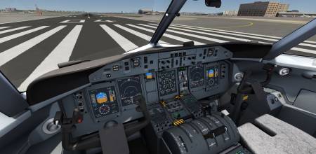
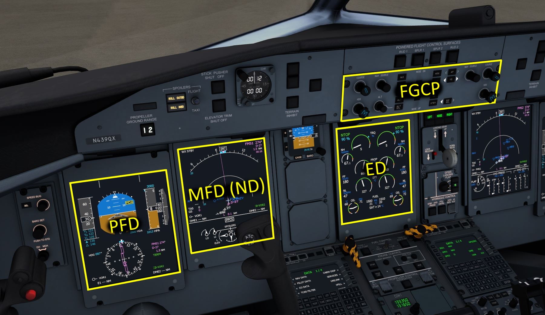
Take your time and look around the Cockpit for a bit. Read the panel names and get an idea where which panel is located. Lets start a bit of a tour through the flight deck of the Q400. Directly in front of the pilot there are two monitors. The left one is the primary flight display (PFD) and the right one is a multi function display (MFD) currently showing the navigation display page (ND) with the flight plan and waypoints on it. The bottom half of the MFD shows the positions of the Primary Flight ControlS (PFCS). In the center of the front panel we find the Engine Warning Display (EWD) that indicates the status of the engines, most interestingly to us: torque (TRQ) precentage and propeller rotation speed (PROP RPM). Directly above the EWD, in the glareshield, you can find the Flight Guidance Control Panel (FGCP) also called autopilot panel, which we will use to interact with the autopilot.
PFD
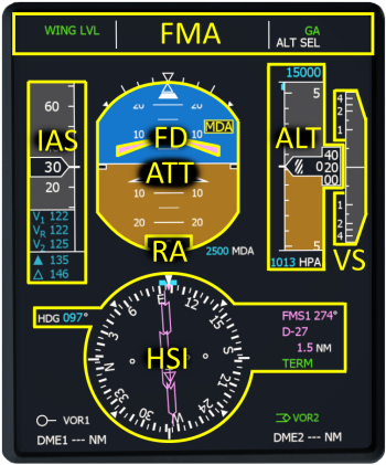
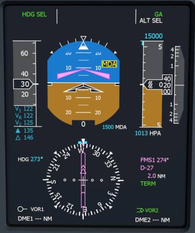
The PFD displays, left to right, the current airspeed, the attitude, the altitude and the vertical speed. In the lower half of the display you find the horizontal situation indicator (HSI). The primary flight display is the most important display in the entire cockpit. For that reason it is place directly in front of the pilot.
The PFD is split into several parts:
- FMA - Flight Mode Annunciator with the lateral flight guidance mode on the left and the vertical mode on the right in green as well as armed modes in white in the second line
- FD - single cue Flight Director that moves up and down to command pitch angle changes and pivots left and right to command bank angle changes
- IAS - Indicated AirSpeed with readouts of V1 (takeoff go-speed), VR (takeoff rotation speed), V2 (takeoff climb speed with engine failure), V FRI (flap retraction speed - solid triangle) and V Climb
- ATT - ATTitude indicator displaying pitch and bank angle as well as side slip (white trapezoid at the top)
- ALT - barometric ALTitude in feet as well as selected altitude at the top as digital readout
- VS - Vertical Speed with a white needle and a digital readout of the current vertical speed above and below the scale in 100 ft/min
- RA - Radar Altitude digital readout of the height above terrain in feet
- HSI - Horizontal Situation Indicator that shows the selected heading on the left as well as a heading bug around the compass rose in the center, current heading is up on the display, a deviation bar to indicate the offset of the selected navigation source and on the right a legend to show which navigation source is selected as well as it's course.
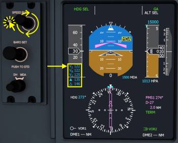
Setting V-Speeds
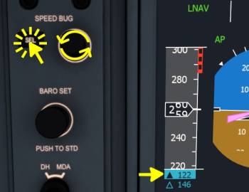
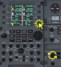
- Click the SELect button next to the PFD to select a line in the v-speeds to edit. Hit the button multiple times to step through the speeds.
- Within 5 seconds move your mouse over to the SPEED BUG knob and use your mouse wheel to increase or decrease the speed in the highlighted line
- Click the SEL button again to move to the next speed.
Note - V1 and VR will be removed from the legend as soon as they are passed in the acceleration phase. They come back after touch down when the speed is decreased again. V2 will be removed when it runs of the speed tape and will also come back during the rollout.
The solid triangle represents the flap retraction speed (V FRI). Above this speed you can safely retract your flaps after takeoff.
The triangle outline is the climb speed (V Climb). After the level off (not below 400ft above the field) you can use it as a target when the one engine has failed.
Setting MDA Marker For Takeoff
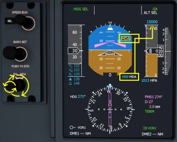
It is quite helpful to set the Minimum Descent Altitude (MDA) marker to 1500ft above the airport elevation. Then we know when to reduce the pitch attitude after the takeoff and start accelerating into the climb phase. Read the current altimeter indication on the right side of the primary flight display (PFD) and add 1500ft, maybe round it up a little bit.
To enter this altitude as MDA
- Rotate the outer knob of the DH/MDA selector left of the PFD to “MDA”. Point at the outer ring of the knob and use your mouse scroll wheel and and scroll up (finger moving upwards)
- Now use the inner knob to change the value of the MDA
- Once you reach this altitude during the initial climb segment the MDA line on the altitude tape will turn blue, the “MDA” label on the attitude indicator will disappear.
EFIS Control Panel
The Electronic Flight Instrument System Control Panel (EFIS Control Panel) can be found forward and left of the throttle quadrant. It has knobs and buttons to control the PFD as well as the MFD (Multi Function Display).
- Mouse over the left or right Bearing knob (BRG) to display bearing needles from different sources on the HSI.
- The current selection made is displayed in the lower left and lower right corner of the PFD as a legend. In the OFF position no needle is displayed at all.
- AUX1 and AUX2 are not installed
- FMS1 and FMS2 require a flight plan to be near by
- VOR1 and VOR2 cannot display a bearing to an ILS
- ADF needles are parked at 3 o'clock (90° off to the right) when no signal is received.
MFD
The Multi Function Displays (MFDs) in the Q400 are capable of rendering different pages that a pilot can chose from. The selection of the pages is done with the Engine and System integrated display Control Panel (ESCP) and the adjustment of the navigation display (map) is done with the Electronic Flight Instrument System (EFIS) control panel. For example, you can zoom in on the map, display the localizer deviation or the flight plan, you can visit system pages or display the PFD or ED instead (display swap).
ESCP
The Engine and System integrated display Control Panel (ESCP) (what a name! I'm not writing that again 
The knobs in the top left and top right of the ESCP panel are the MFD1 and MFD2 revision selectors which each have 4 options: PFD, NAV, SYS and ENG and control the left and right side MFD mode.
- Move you mouse cursor over the knobs and rotate them with the mouse wheel.
With the selector in PFD the MFD displays the primary flight display, e.g. in case the left screen is broken.
In NAV the navigation display is displayed.
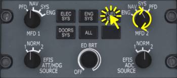
SYS displays a system page. With the pushbuttons in the center of the panel the different pages for electrical systems (ELEC SYS), engine systems (ENG SYS), fuel system (FUEL SYS) and doors page (DOORS SYS) can be visited. With the “ALL” button the pages are stepped though, one at a time per click.
- Mouse over the MFD2 selector and your your scroll wheel
- Click a button in the center to change the page
With the selector in ENG the engine display is displayed on the MFD in case the center screen is broken for example.
EFIS Control Panel
When the MFD revision selector is in the NAV mode (default Aerofly setting for both MFDs) then the navigation display (ND) is shown on the MFD.
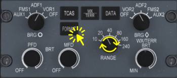
- Click the FORMAT button to view the FULL MODE of the navigation display, a north up plan mode
- Hold down the FORMAT button for 1 second. This option hides the flight plan and displays the localizer deflection instead.
- Mouse over the RANGE knob and rotate your scroll wheel to increase or decrease the range on the map. Scroll down to close in on your aircraft, scroll up to increase the range and see further into the distance
- Click the DATA button multiple times to show navigation aids (NAV), airports (APT), both (NAV & APT) or neither on the map
ED
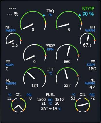
The Engine Display shows the most important engine related parameters. It is located in the center of the flight deck to be visible easily by both pilots.
- Top left and top right: Engine Rating, name and maximum torque percentage.
- TRQ - current torque percentage which indicates the current power created by the engines as a percentage of the current rating. Note - 100% with 850 RPM is creates less power than 100% with 1020 RPM. The actual power output of the engine is the product of propeller rotation speed and torque!
- NH - The High pressure rotation speed is the engines most inner core rotation speed, high pressure compressor and turbine shaft rotation speed. Displayed as fraction of maximum design speed.
- PROP/NH: Propeller Rotation speed in rotations per minute. On the ground RPM is maintained at 660RPM, during takeoff MAX 1020 RPM is used
- FF - Fuel Flow consumed by the engine, in kilogram per hour.
- ITT - Indicated Turbine Temperature in degrees Celsius
- NL: Low Pressure rotation speed, outer core engine low pressure compressor and turbine shaft rotation speed. Displayed as fraction of maximum design speed.
Other parameters displayed are: Oil temperature and pressure, fuel in each wing tank and the fuel temperature, Static Air Temperature (SAT).
The display also displays “REDUCED NP LANDING” at the top (described further down) and the status of the autofeather “A/F SELECT” or “A/F ARM” under specific conditions.
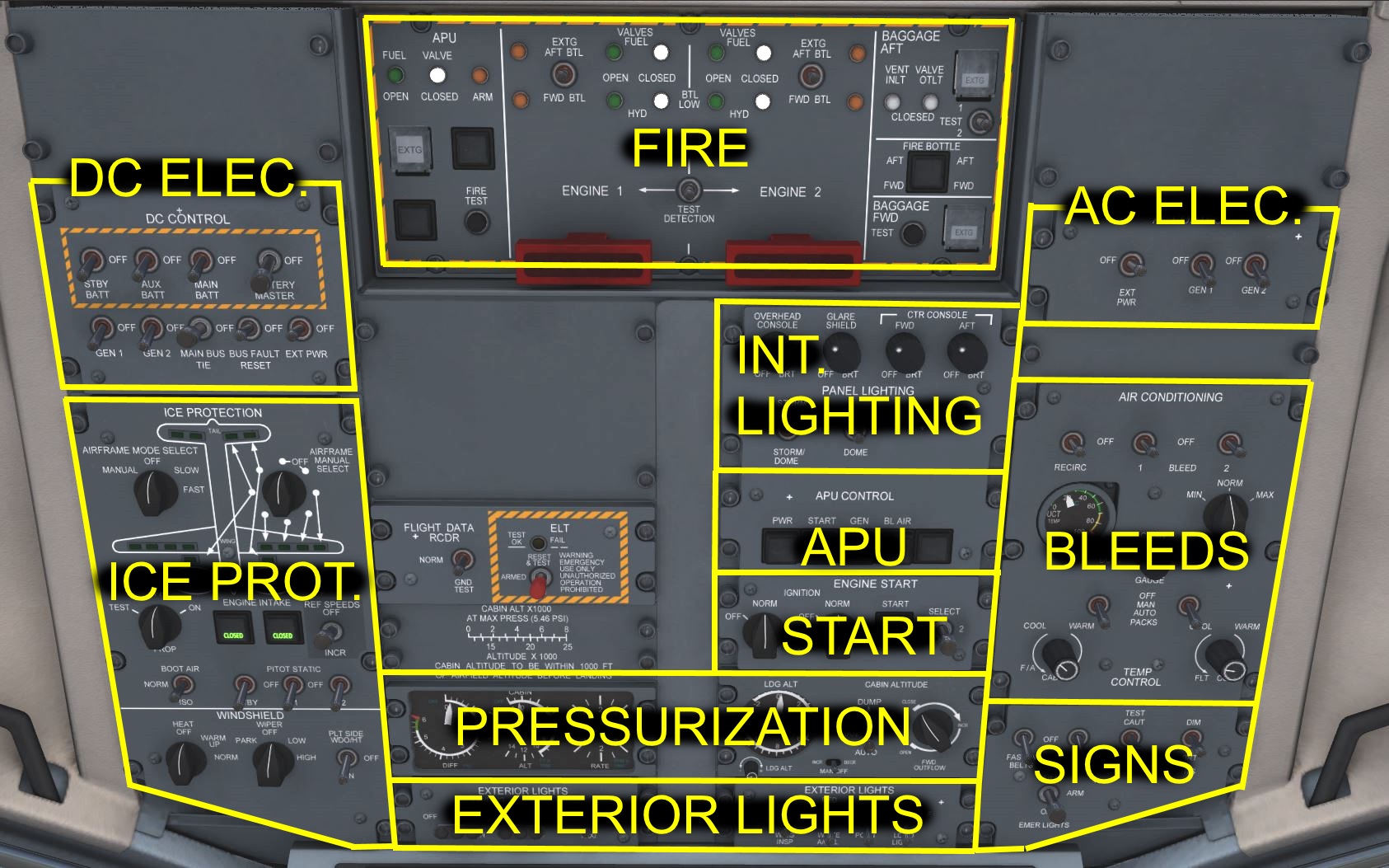
Overhead Panel
Throttle Quadrant
The “throttle quadrant” in the Q400 moves a lot of levers into one location. From left to right the quadrant features:
- ELEVATOR TRIM indication - If you don't have a control axis assigned for this you can use the mouse wheel over the indicator to adjust the trim ND (nose down) or NU (nose up). When you have an analog axis assigned please be ready to retrim the aircraft when ever you change the position of the aircraft with the location dialog. If you don't assign an axis the trim will be set for takeoff, landing or cruise depending when you select these starting locations with the location dialog.
- EMERGency/Parking BRAKE lever - Click the lever to toggle the parking brake
- POWER levers - can be assigned in the control settings as “Throttle” 1 and 2 as well as “Thrust reverse” 1 and 2. Both levers can be dragged with the mouse together by holding down the right mouse button or individually by holding down the left mouse button. The forward throttle controls the range from DISC to full RATING power with FLT IDLE being the minimum allowed position in flight. Reverse moves the levers aft of DISC towards FULL REV(erse).
- CONTROL LOCK - click on black bar in front of the power levers to set and remove the gust lock. This should only be done on ground as is locks the ailerons in neutral. When the power levers are advance to far the gust lock in Aerofly is automatically removed so that you can take off even if you forgot to remove the gust lock.
- PROPeller levers - are also called “condition levers” since they not only affect the propeller rotation speed but also the rating of the engine (maximum torque value). These levers can be assigned in the control settings as “Propeller Speed” 1 and 2 or can be adjusted with the mouse wheel. Both levers can also be dragged with the mouse: together by holding down the right mouse button or individually by holding down the left mouse button.
- FLAPS lever - Affects the target position of the flaps. Flap 35 can only be recommended for very short runways, typically flaps 15 is plenty. The flap lever can be adjusted with the mouse scroll wheel or by holding down the left mouse button and moving the mouse to drag the lever. There are also assignable axis or buttons for the flaps in the control settings. Default key commands are “F” and “Shift+F”.
In the pedestal we find the Audio and Radio Control Display Units (ARCDU 1 and2), the aileron and rudder trim, the Multi Function Display (MFD) control panel and the Weather Radar controls.
ARCDU
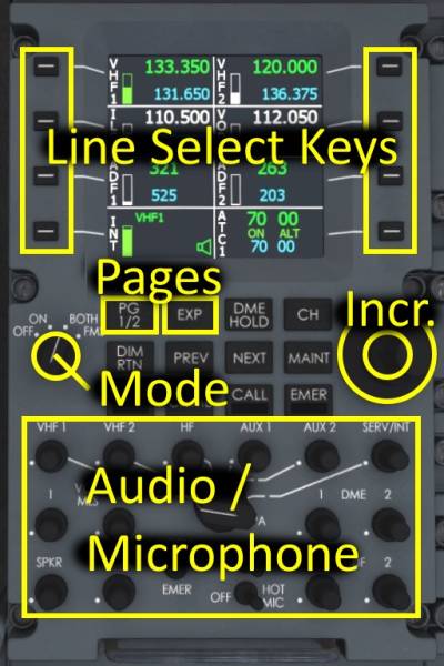
The Audio and Radio Control Display Units (ARCDU 1 and ARCDU 2) are the Q400's interface to the navigation receiver frequencies and audio levels as well as the ATC/TCAS modes and microphone settings.
Automatic Frequency Tuning (FMS Mode)
The ARCDUs have the capability to tune the ILS frequencies of the destination airport fully automatically. They also set the course which is not possible in the real world aircraft. Automatic tuning is only performed when the mode selector of the ARCDU is in “FMS”. The left ARCDU (ARCDU 1) can tune ILS1 and the right ARCDU (ARCDU 2) tunes ILS2 if they are set to “FMS” mode respectively.
Manual Modes (ON, BOTH)
The left ARCDU (ARCDU 1) is assigned for the left side frequencies (VHF1, VOR1/ILS1 and ADF1). The right side controls all receivers with the number 2 at the end.
ON - Only editing of the the onside frequencies is allowed
BOTH - The frequencies of the left and right side can be tuned.
Manual Frequency Tuning
- Set the mode switch to “BOTH” on the left and right ARCDU using the mouse wheel or left or right mouse button
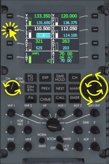
- Select the frequency that you want to edit with the line select keys on the side of the display by clicking on the button. Note - After 5 seconds the selection is reset and the highlight is no longer visible, press the line select key again
- Use the fine and coarse knob to adjust the standby frequency, again using your mouse wheel
- To transfer the frequency into the active field click the line select key a second time
Note - When FMS mode is selected or the mode selector isn't on BOTH and a frequency of the opposite side is selected with the line select buttons then the label will flash. Change the mode to BOTH on each ARCDU device to gain full authority.
ATC/TCAS
Transponder status
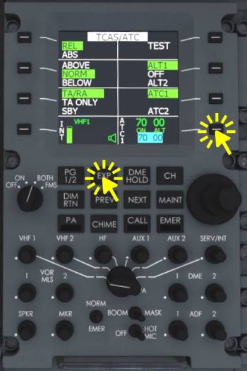
- Hold down the lower right line select key (next to ATC1 label) for one second to toggle the transponder mode from OFF to ON ALT and back.
ATC/TCAS details
- Left click the lower right line select key
- Click the “EXP” button to visit the expanded ATC/TCAS page to see more options
- Click individual line select keys multiple times to step through the displayed options
- Press the “PG 1/2” mode to exit the expanded page
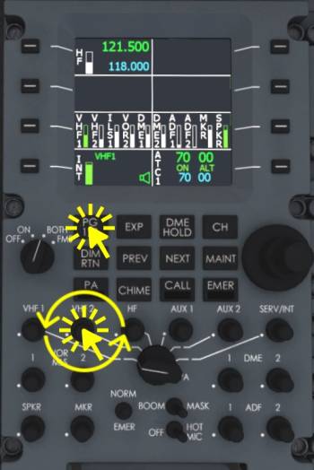
Note - Similarly you can access expanded pages for VHF1/2, NAV1/2 and ADF1/2. There is also a PG 1/2 button to access page 2 of the ARCDU.
Volume Levels
At the time this text was written no audio reception was implemented yet. So this is more in preparation for later.
- Click the “PG 1/2” button to access the second page. Here you can monitor the volume levels for each receiver.
- Use the scroll wheel of your mouse over the knobs on the lower part of the device to adjust the levels.
- Click these knobs to activate or deactivate the audio reception of the individual channel
Engine And Prop Control Panel
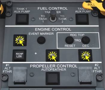
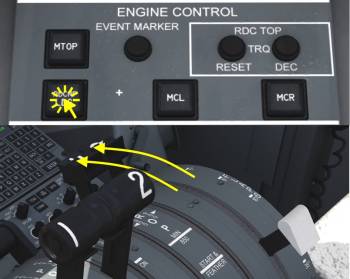
There are several derates for the turboprop engines that the pilots of a Q400 can chose from. The selection is made with a movement of the PROP/condition levers and the available pushbuttons for engine control in front of the throttle quadrant. The available affect the maximum torque and therefor maximum power of the engines. We modeled all of the Q400 derates which are:
- MTOP - Maximum TakeOff Power with 1020 RPM
- NTOP - Normal TakeOff Power with 1020 RPM
- RDC TOP TRQ - NTOP with additional Reduced Top Torque up to 10% decremented with 1020 RPM
- MCL - Maximum CLimb Power with 900 or 850 RPM
- MCR - Maximum CRuise Power with 900 or 850 RPM
- - - - : no derate applicable (engine shut down)
When moving the condition levers the default selections are restored. The default engine derates are mapped to the lever position like this:
- MAX 1020 - moving the lever to this position selects NTOP
- 900 - selecting 900 RPM sets MCL
- 850 - selects MCR
- START & FEATHER - selects NTOP
- CUT OTT - none
Engine Rating And Noise Reduction
After moving the condition levers to the desired rotation speed the default engine derate can be overwritten with the push buttons on the engine control panel:
- With the PROP levers at MAX 1020 RPM you can click this button to set full 100% takeoff power
- Click the MCL button to overwrite the default cruise power with climb power (MCL) when your PROP levers are at 850 RPM or 900 RPM. Is used in the real world for a noise reduced climb with 850 RPM and max climb power.
- Click the MCR button to override the default climb power with cruise power (MCR) when your PROP levers are at 850 or 900 RPM. Is typically used when cruise altitude is reached and levers are already at 850 RPM due to a noise reduced climb.
Reduced Takeoff Power
To save fuel, engine wear and noise emissions a takeoff with reduced takeoff power can be performed.
- Set the condition levers to MAX 1020 RPM
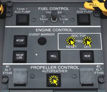
- Click the “DEC” button on the RDC TOP section multiple times to decrease the maximum power rating for takeoff to a maximum of 10% torque reduction.
- Click the reset button to reset normal takeoff power (NTOP)
Autofeather
- Click the AUTOFEATHER button on the PROPELLER CONTROL panel to toggle the state of the automatic feathering in case of engine failure. At the time this tutorial was written auto feather was not not implemented.
Reduced Propeller Rotation Speed Landing For Noise Reduction
To reduce cabin and airport noise during the approach it is common to use a reduced rotation speed of 850 RPM. To be prepared for a go-around with full power available the aircraft is prepared as follows:
- Move the PROP levers to 850 RPM if not already in that position from cruise and descent
- Click the RDC NP LDG pushbutton
- Move the PROP levers to MAX 1020 RPM and limit the power demand to below 50% within 15 seconds.
Note - To cancel this state either increase power above 50% to perform a go around or push the RDC NP LDG pushbutton a second time.
FGCP And Autopilot Modes
The Flight Guidance Control Panel (FGCP) is the interface to the autopilot and flight director. The left column of push buttons to the left of the vertical wheel in the center are used to change the vertical modes (pitch up and down). The buttons on right column affect the lateral steering mode (bank left or right).
In the center of the panel a vertical scroll wheel can be found that is used to manipulate the selected pitch, selected indicated airspeed or selected vertical speed, which ever mode is currently selected. The direction of the scroll wheel is always in the same manner, scroll the wheel up with the finger and you find the aircraft pitching down, rotating in a similar fashion as the wheel. And if the wheel is scrolled downwards the aircraft follows that rotation and pitches up.
In the lower left and lower right corner of the panel you can find the heading knobs (HDG). These knobs are rotated with the mouse wheel to change the selected heading. Use either heading knob, they are linked together in our simulated aircraft.
Brief explanation of the purpose of each knob:
- COURSE - changes the selected course on either primary flight display (PFD). The knob has no effect when the navigation source is FMS1 or FMS2
- NAV SOURCE - these knob changes the selected navigation source of the left and right PFDs respectively. Available sources are: FMS1, NAV1, NAV2, FMS2. Depending on weather the NAV1 or NAV2 frequencies are VOR or ILS frequencies the displayed sources are VOR1/ILS1 or VOR2/ILS2. To fly an ILS approach, with the ILS1 frequency set, the left NAV SOURCE knob has to be rotated to ILS1 and then the APPR button can to be pressed. To follow the lateral flight plan the source has to be selected to FMS1 or 2 and then the “NAV” button can be used to select LNAV
- HDG - changes the selected heading on both PFDs. The selected heading is never synchronized in the Q400 and has to be re-adjusted manually.
- ALT - increases or decreases the selected altitude. Note the arrow to the ALT SEL button as it is important to press ALT SEL whenever you plan to level off at the selected altitude!
- Vertical Wheel - NOSE DN / NOSE UP. As mentioned above this changes the selected pitch, speed (IAS) or vertical sped.
Left buttons (vertical mode):
- IAS - When pressed (left click) the vertical mode changes to Indicated AirSpeed mode (IAS). The current airspeed is used as a reference to pitch the aircraft up or down and therefor reduce or increase speed. The vertical wheel in the center can be used to change the selected IAS. Press again to return to PITCH HOLD.
- VS - Changes the vertical mode to Vertical Speed hold (VS) when clicked. At engagement the current vertical speed is synchronized and can be changed using the vertical wheel. Depressing the button again changes the vertical mode back to PITCH HOLD.
- VNAV - when the aircraft is in cruise and the selected altitude is lower than the current altitude this button may be clicked to arm the Vertical NAVigation. When the vertical profile, as observable left of the altitude tape on the PFD, is intercepted the armed VNAV engages to VNAV PATH. The mode can be disarmed or disengaged by pressing the VNAV button a second time. If it was engaged the vertical mode will revert to PITCH HOLD.
- ALT - Commands an instant level off at the current ALTitude and changes the vertical mode to ALT (HOLD). The target altitude is the altitude at the time of engagement. The selected altitude is not taken into account. A second click on this button will restore the PITCH HOLD mode.
- ALT SEL - This push button can be clicked with the left mouse button to arm the selected altitude. Any vertical mode (except glide slope) will be aborted and the active vertical mode changes over to ALT* (altitude acquire) followed by ALT (altitude hold) once the selected altitude has been reached. Clicking the button with the right mouse button simulates depressing the real world button for for one second. Then the ALT SEL is removed and the currently active vertical mode will not end in an altitude capture at the selected altitude. Note: When engaging a new vertical mode to fly towards the selected altitude the pilot has to press this button manually. Otherwise the aircraft will not capture the selected altitude and fly right through it. This is something that needs attention each time the selected altitude was changed (therefor the little line between ALT selector and ALT SEL pushbutton)
Right buttons (lateral mode):
- HDG - A click on the heading button engages the heading select (HDG SEL) lateral mode. With the HDG SEL lateral mode engaged the flight guidance computer will command the autopilot to do a left or right turn to steer towards the selected heading value. The selected heading can be changed with the HDG knobs as described above. This HDG SEL mode mustn't be confuse with heading hold (HDG HOLD) where the heading at engagement is maintained and the selected heading is disregarded. A second click on the HDG pushbutton will cause the basic lateral mode to engage.
- NAV - Depending on the the selected NAV SOURCE a press on this button will either engage LNAV HDG SEL (FMS1 or 2 selected) or arm VOR (NAV1 or 2 selected). When the heading intercepts the flight plan and the lateral deviation is small enough the LNAV HDG SEL will switch to LNAV and the aircraft will follow the lateral flight plan. When VOR is armed and the needle of the NAV1 or NAV2 receiver (depending on the selected nav-source) leaves the full deflection the VOR radial or localizer will be captured and maintained, even over the station. Modes VOR* and VOR OS are currently built into the VOR mode and not indicated separately as in real world.
- APPR - Again, depending on the selected NAV SOURCE this buttons will do two things: either arm FMS APProach or ILS/VOR APPRoach. With FMS1 or 2 selected this button will arm the LNAV/VNAV APPRoach with similar capturing conditions to LNAV and VNAV, only ALT SEL will not cause a level off. This can be used to follow the flight plan all the way down to the runway threshold. But when NAV1 or NAV2 is selected as a navigation source the ILS approach will be armed (LOC + GS) or the just the localizer (LOC) when no glide slope is available.
- BC - captures the localizer on the reciprocal course. This is not implemented yet.
- STBY - Hides the flight directors and clears all modes when the autopilot is not engaged. Used to clear up the flight director and set it to standby. If the autopilot is connected this button will cause the vertical mode to revert to PITCH HOLD and the lateral mode to basic lateral mode.
- AP - Autopilot master. Click this button to engage or disengage the autopilot. When the autopilot is set to on the yaw damper will also engage.
- YD - Engages or disengages the Yaw Damper. As long as the autopilot is engaged this button is ineffective. When engaged the yaw damper reduces uncommanded yaw rates and stabilizes the fuselage longitudinal axis.
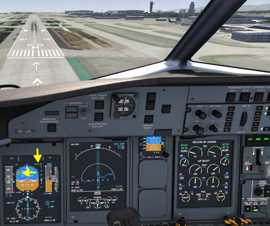
- HSI SEL - Pressing this button selects either the left PFD or the right PFD for the autopilot source. When the arrow is pointing towards the left the pilot's navigation source is used for the autopilot. When the arrow points to the right the first officers navigation source is used instead. When both PFDs have NAV1 and NAV2 selected and NAV1 and 2 receivers are tuned to the same frequency and set to the same course and other conditions are met (e.g. DH left and right are identically and RA is below 1000ft) then both arrows will be illuminated at the same time and DUAL FD is indicated on both PFDs. In this configuration it is safe to fly an ILS Category 2 approach down to 100ft. The autopilot has to be disconnected prior to landing since the Q400 is not capable and not certified for a fully automatic landing.
Basic Lateral Mode
Whenever a lateral mode is disengaged by pressing the button a second time or when the STBY button is pressed or when the FD is engaging in flight the basic lateral mode engages. When the bank angle at that time is below ~6 degrees the wings are leveled (WING LVL) followed by a heading hold (HDG HOLD) and present heading is maintained. Above that threshold the current bank angle is maintained (ROLL HOLD). Tutch Control Steering (TCS) to manipulate this bank angle is not implemented yet.
Heading Select (HDG SEL)
- Mouse over either the left or right heading knob (HDG) and use your scroll wheel up and down to change the selected heading right or left. The selected heading can be seen on either PFD or either MFD (given navigation display (ND) is displayed as per default)
- Left click the “HDG” button once
Vertical Speed (VS)
- Click the “VS” button
- Use your mouse wheel over the vertical wheel to adjust the selected vertical
Indicated Airspeed Hold (IAS)
- Click the “IAS” button
- Rotate the vertical wheel to change the selected airspeed
Arming Altitude Acquire (ALT SEL)
Unlike most modern airlines the Q400 engineers decided that the altitude capture function should only engage when pilots explicitly press a button to arm it. Since it is very unique for an autopilot we modeled this in the Aerofly FS aircraft but this also means that you have to check if ALT SEL is armed in white on the PFD every time you changed the selected altitude. Typically a press on the ALT SEL pushbutton is required when you are maintaining the current altitude and want to climb or descent to another altitude. Then another vertical mode has to be engaged and the selected altitude has to be changed and ALT SEL needs to be pushed.
On the upside, if you ever wish to prevent a level off you can disarm the altitude capture (ALT SEL) by holding the ALT SEL button for 1 second.
When ALT SEL is armed in white on the PFD the active vertical mode will change to ALT* (altitude acquire) to capture the altitude followed by ALT to maintain that altitude.
- Use the scroll wheel of your mouse over the “ALT” knob on the autopilot panel. Select the initial altitude of the departure or even your cruise altitude. For our short tutorial flight from San Diego to Los Angeles select 15,000ft. This will be our cruise altitude.
- Click the ALT SEL pushbutton on the autopilot panel to arm this selected altitude. If we don't do this the aircraft won't stop climbing.
Navigation Source Selection
There are four possible navigation sources in total: FMS1, NAV1, NAV2 and FMS2. The selected sources are changed with the NAV SOURCE knobs on the FGCP as well as the HSI SEL button on the same panel.
FMS1 and 2 are the flight management systems of the Q400 that contain the lateral and vertical flight plan.
NAV1 and NAV2 are navigation receivers that can be tuned to a certain frequency to receive VOR or ILS localizer signals as well as Glide Slope (GS) information and distance to the station with their distance measurement equipment (DME). Depending on the frequency NAV1 and NAV2 will be displayed as VOR1 or ILS1 and VOR2 or ILS2.
The selection of a navigation source is done individually on each of the two HSIs (left and right PFD). The flight guidance (autopilot) uses either the left or right side nav-source as indicated by the HSI SEL arrows on the autopilot panel (FGCP) as well as an arrow on the PFD not in use (pointing to the selected side).
- Move the mouse over the left and right NAV SOURCE knob and rotate your mouse wheel to change navigation source of the left and right side PFD individually
- Click HSI SEL to toggle between left and right PFD source
The currently selected navigation source for the HSI is displayed on the PFD, in a small legend next to the HSI. The selected course and course deviation change depending on the nav-source. The legend is colored in magenta for “FMS” navigation sources and cyan for “NAV” navigation sources. If the pilot and copilot both select the same navigation source the color for the nav source will be yellow, e.g. to warn both sides not to change any course or frequency without communicating with the other person.
Follow VOR/ILS (VOR, LOC + GS)
- Leave the ARCDU mode in FMS for automatic ILS tuning OR switch it to BOTH and manipulate the NAV1 (or 2) frequency (usually left NAV1, right NAV2).
- Set the course using the COURSE knob on the FGCP.
- Rotate the NAV SOURCE knob on the FGCP with the mouse wheel until it displays the tuned ILS1 (or 2).
- Press the APPR button on the FGCP to arm the LOC and GS, OR press the “NAV” button to follow just the localizer, lateral mode displayes as “VOR” in this case.
Lateral Navigation With Flight Plan (LNAV)
- Rotate the NAV SOURCE with the mouse wheel until FMS1 or FMS2 are visible on your PFD in front of you.
- Look at the HSI SEL arrow and press it, if necessary, to point in the direction of your PFD.
- Click the “NAV” button
Note - If LNAV HDG SEL is indicating on the FMA turn the heading knob towards the route to get back on track. LNAV should engage automatically when the route is close enough and can be captured.
Climb And Descent Shedule
IAS Climb
Typically, during climb, IAS is used up to a certain altitude before switching back to PITCH HOLD. Three climb profiles can be chosen from:
- High speed climb (Type 1): IAS 210 kts up to FL 150
- Intermediate speed climb (Type 2): IAS 185 kts up to FL 200
- Low speed climb (Type 3): IAS 160 kts up to FL 250
After that speed is either gradually reduced by about 5kts per 1000ft or the IAS mode is deselected by pressing the IAS pushbutton again. In the following PITCH HOLD mode the pitch attitude is lowered to about 5 degrees.
IAS Descent
During the descent either vertical speed, IAS or VNAV are used. It is also be possible to use PITCH HOLD during some phases in the descent.
For the descent the indicated airspeed mode (IAS) there are multiple descent types:
- High speed descent (Type 1): IAS VMO - 10 kts (should be limited to -2000ft/min for cabin pressure differential)
- Intermediate speed descent (Type 2): IAS ~200 kts
- Low speed descent (Type 3): IAS 160 kts
- and even more modes we won't go into here…
Vertical Navigation (VNAV) Descent
The vertical flight plan (VNAV) can only be used for the descent planning. The autopilot will fly a fixed geometric path towards the final approach fix and we have to manage the speed ourselves. We can reuse the speed profiles from the IAS descent (see above). Keeping the power lever a bit above FLT IDLE we can, for example, maintain around 240 kts which results in a nice and stable descent all the way into the approach without the need to reduce speed at any point in the descent.
- For this select FMS1 or 2 as described above
- Prior to the <TOD> on the map select a lower altitude than you are currently flying at
- Press the ALT SEL to arm the altitude capture at the end of the descent.
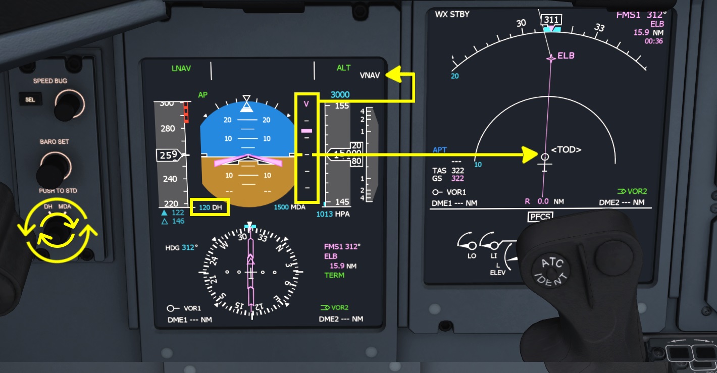
- Click the “VNAV” key on the FGCP. VNAV indicates in white on the flight mode annunciator (FMA) on the primary flight display (PFD) in the top right corner.
VNAV PATH will engage once the vertical profile is intercepted. To intercept use any other vertical, e.g. vertical speed and either increment the descent rate if you are above profile or reduce sinkrate or even level off when the vertical deviation shows that the flight plan is above you.
Flight Management System (FMS)
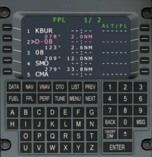
The Q400 uses the Universal FMS which is also used in the Learjet 45 and in the specific 737-500 simulated in Aerofly FS. The FMS is described in detail on the Universal UNS-1 wiki page.
Warning Sounds
The Q400 has a lot of warning sounds and if you have played around with it in Aerofly already you probably heard at least three or four of them.
Gear Warning
A constant medium pitch beep sound is heard when the aircraft logic circuits think it should the gear should be down in the current configuration. Often this warning is heard when the power is reduced to idle low to the ground.
Extend the landing gear by either clicking the lever in the cockpit or pressing your button or key assignment (default key: “g”).
Beta Warning Horn
When the power levers are retarded below the FLT IDLE detent in flight a loud alternating high-low pitch warning sound is heard (oioioi…). This warning indicates that you should increase your throttle lever until it snaps into the FLT IDLE position. Since the Q400 is equipped with propellers that can pitch flat (DISC 90° to flight direction) and even backwards (REV) to create reverse thrust it is not a good idea to try and pull the power levers aft of the flight idle where they could act as two circular 4.1 m diameter airbrakes.
Keep the power levers above FLT IDLE during the entire flight. Also, during flare, don't reduce the power to FLT IDLE, keep the power in during the flare to avoid falling from the sky.
Altitude Alert
When approaching the selected altitude a high pitch beep sound can be heard. This is just alerting the pilots that the aircraft will level off in about 1000ft and that the pilots should be ready to re-adjust the power, since the Q400 doesn't have an auto throttle system. When the selected altitude is flown through and the aircraft wasn't leveled out the sound is triggered again 250ft below or above the selected altitude as to warn pilots they are diverting from the selected altitude.
When flying around for fun or are currently resetting the selected altitude just ignore this warning. When the autopilot is flying make sure that “ALT SEL” is armed in white so that the altitude capture function is activated when you hear this sound. Then adjust the power once the altitude captures.
If you fly on autopilot and hear the warning two times in a row you probably just shot through the selected altitude. Make sure to arm “ALT SEL” next time. For now you have to change the vertical mode to get back to altitude.
Pitch Trim
When the pitch trim is moving for more than two seconds a constant ticking sound is heard to warn the pilots of a potential pitch trim run away.
If you are manually holding the pitch trim button release the button for a second to stop the warning or just ignore it until you are finished trimming.
Stall Warning
When the aircraft's speed is low (in the red low speed area) or the angle of attack is too high the stick shaker triggers which is audible as a rattling sound.
Reduce the angle of attack by reducing back pressure on the yoke and add power to increase airspeed.
Overspeed
A constant medium pitch beeping sound is set off when you exceed the maximum operating speed of the Q400. This maximum speed changes with the altitude. Look at the PFD speed tape and notice the red overspeed tape.
Gently pull on the yoke to recover from the overspeed and/or reduce the power lever position to FLT IDLE. Check the speed chart on the left side window frame for more the maximum operating speeds under certain conditions and with individual configurations.
Takeoff Configuration Warning
On the ground a medium high pitch pulsing warning is triggered when the power levers are advanced for takeoff power and the aircraft configuration is not okay for takeoff.
- Check your flap position, it should be between 5 and 15 degrees for takeoff.
- Set the PROP levers to MAX 1020. Note When ever you are on the ground and are currently not in the process of shutting down or starting the engines leave the PROP levers at 1020.
- Center your tiller, a large deflection of the nose gear is seen as a problem.
Master Warning & Caution
A short medium pitch beep is heard when a caution goes off. This is accompanied by a flashing master caution light on the right side of the glareshield. Click the warning light to stop the flashing and look up to the caution and warning panel (underneath the overhead panel) to read the caution message.
A tripple ding is heard when a master warning is triggered. Immediately check the warning panel. When you shut down either engine a few master warnings are to be expected. The usually can be ignored when you are on the ground.
Bombardier Dash 8Q-400 Flight Tutorial
Flight Plan
The flight for this tutorial is taking us from San Diego runway 27 to Los Angeles runway 25R along the west coast, northbound. After adding the start and end to our route we also add the SAN, NFG and ELB VORs to the route to that the flight plan looks like this (with a few automatically generate waypoints left out):
KSAN RWY27 SAN NFG ELB KLAX RWY25R
This route is 103.1 NM long and will take us about 25 minutes. The cruise altitude is going to be 15,000ft and we're only going to cruise for a short time.
Wind: None or slight West-wind
Time of day: 0000Z (4pm local)
Flight Preparation
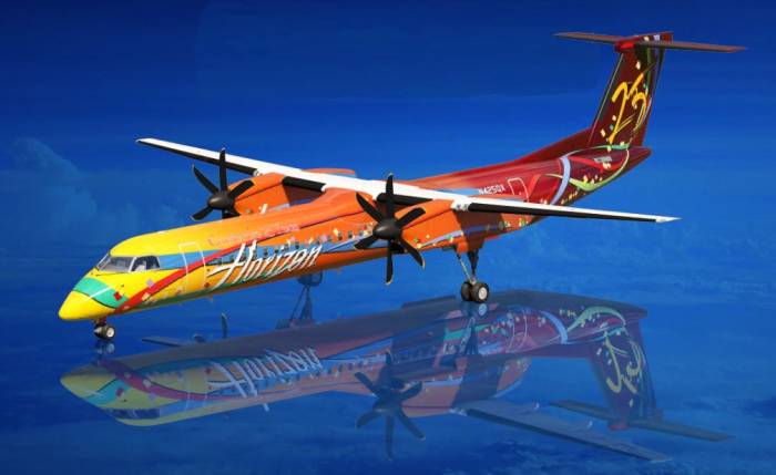
After setting up the tutorial route from San Diego to Los Angeles select the Bombardier Dash 8Q-400; in the fresh green or colorful celebration Horizon livery and use the location dialog to place the aircraft in San Diego on the ramp (white aircraft symbol).
In the control settings in the Autopilot section we need to assign a key/button to the TOGA button (“Take off / go around mode”), because we will need this button later.
Move the throttle to idle and if you have your condition levers assigned, move them all the way forward now. Then press “Start” to begin the flight.
Engine Start
You can skip this part if you don't want to do this, the engines should already be running at this point But if you want to start the engines for yourself go ahead and move your condition levers all the way down to FUEL OFF.
* Item should be completed by default
| Engine Start Procedure | |||||
|---|---|---|---|---|---|
| No. | Location | Panel Name | Action | Remarks | |
| 1 | Pedestal | Throttle Quadrant | PARKING BRAKE | ON | * |
| 2 | Overhead | EXTERNAL LIGHTS | ANTI COLLISION | ON RED | |
| 3 | Overhead | Signs | EMERGENCY LIGHTS | ARM | * |
| 4 | Overhead | Signs | FASTEN BELTS | ON | * |
| 5 | Overhead | Signs | NO SMOKING | ON | * |
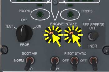
| 6 | Overhead | ICE PROTECTION | ENGINE INTAKE 1&2 | SET OPN | Press each button 1x |
| 6 | Overhead | AIR CONDITIONING | RECIRC | ON | |
| 7 | Overhead | AIR CONDITIONING | BLEED 1&2 | OFF | * |
| 8 | Overhead | APU CONTROL | PWR | ON | Wait for self test |
| 9 | Overhead | APU CONTROL | START | ON | Wait for green RUN |
| 10 | Overhead | APU CONTROL | GEN | ON | |
| 11 | Overhead | APU CONTROL | BLEED AIR | OFF | * |
| 12 | Overhead | DC CONTROL | MAIN BUS TIE | TIE | |
| 13 | Overhead | ENGINE START | IGNITION L&R | NORM | * |
| 14 | Overhead | ENGINE START | SELECT | 1 | |
| 15 | Overhead | ENGINE START | START | PUSH | |
| 16 | Pedestal | Throttle Quadrant | PROP LEVER 1 | START & FEATHER | Wait for starter cut out (50% NH) |
| 17 | Overhead | ENGINE START | SELECT | 2 | |
| 18 | Overhead | ENGINE START | START | PUSH | |
| 19 | Pedestal | Throttle Quadrant | PROP LEVER 2 | START & FEATHER | Wait for starter cut out (50% NH) |
| After Start procedure | |||||
|---|---|---|---|---|---|
| No. | Location | Panel Name | Action | Remarks | |
| 1 | Overhead | APU CONTROL | GEN | OFF | |
| 2 | Overhead | APU CONTROL | PWR | OFF | |
| 3 | Overhead | DC CONTROL | MAIN BUS TIE | OFF | |
Preparation Of The Glass-Cockpit
Setting MDA Marker For Takeoff
We're going to set the MDA bug to 1500ft over the airfield elevation to know when to transition to the climb phase. The steps necessary for this have already been shown in the introduction to the flightdeck of the Q400, here they are again. For San Diego which is only barely above sea level we're just going to use 1500ft for the MDA setting.
To enter this altitude as MDA
- Rotate the outer knob of the DH/MDA selector left of the PFD to “MDA”. Click the outer ring or use your scroll wheel on the mouse and scroll up (finger moving upwards)
- Now use the inner knob to change the value of the MDA
- Once you reach this altitude during the initial climb segment the MDA line on the altitude tape will turn blue, the “MDA” label on the attitude indicator will disappear.
Autopilot Actions Before Takeoff
We have to fly the takeoff manually but we have the option to prepare the flight guidance system in advance to reduce workload in the initial segment right after lift off, where things are very hectic. These steps might all be completed already and you can skip a lot of these steps to prepare the autopilot!
First we will select the FMS1 navigation source on our PFD to have our flight plan available right away. As described in the flight deck introduction these are the required actions on your side to achieve this:
- Make sure the HSI select is pointing to our PFD, click it if it need to be toggled
- Use the onside NAV SOURCE knob to step through the navigation sources available. The left knob affects the left PFD, the right knob the right PFD.
TakeOff GoAround (TOGA) Mode
In the control settings of the Aerofly FS there is a control assignment in the autopilot controls for “TakeOff GoAround Button (TOGA)”. Press this button now. If you don't want to assign this you can also depress the “HDG” pushbutton. Note how the flight director on the PFD came alive and the active lateral mode “WINGS LVL” was selected. The vertical mode “GA” is also activated but the selected altitude is not armed yet. And our selected altitude may be off.
- Use the scroll wheel of your mouse over the “ALT” knob on the autopilot panel. Select the initial altitude of the departure or even your cruise altitude. For our short tutorial flight from San Diego to Los Angeles select 15,000ft. This will be our cruise altitude.
- Click the ALT SEL pushbutton on the autopilot panel to arm this selected altitude. If we don't do this the aircraft won't stop climbing.
Heading Select (HDG SEL) For Takeoff
At this point we are not going to engage LNAV, instead we are going to use HDG SEL and the departure runway heading for takeoff.
- Click the “HDG” button to change the lateral mode to “HDG SEL”
- With the mouse cursor over the HDG knob on the lower left or lower right knob of the panel, use your scroll wheel to change the selected heading. For San Diego Runway 27 this it should be set to 273°.
Ready State
When all these actions for the autopilot have been completed the primary flight display should indicate the modes “HDG SEL” with a selected heading of 273° in this case, GA as active vertical mode and ALT SEL armed with the selected altitude at 15,000ft for this flight.
If you accidentally pressed the wrong button just press the “STBY” button on the autopilot panel to clear all active modes. Then try again. You could also takeoff with PITCH HOLD as active vertical mode and manually set the 9 degrees pitch up with the vertical wheel. When the autopilot engages it will synchronize the pitch attitude anyway.
Taxi Preparations
We're now preparing the aircraft for taxi and takeoff.
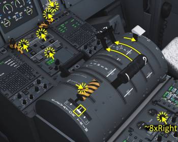
- Set the parking brake by clicking on the orange/black striped lever for the emergency/parking brake or by pulling the lever with the left mouse button held down. The parking brake is set when the lever is in the aft position as shown in the screenshot
- Set the PROP levers to MAX 1020 all the way forward by either moving your assigned controls or by holding down the right mouse button and moving the mouse to drag both levers at the same time.
- Set flaps to 5° by scrolling down once over the lever with the mouse wheel or by grabbing the lever with the left mouse button and moving the mouse or with any assigned key commands (default key “f”)
- Move your mouse over the elevator trim indication and scroll with your mouse wheel to set the trim to the takeoff range or use the assigned pitch trim input (should already be completed)
- Set the rudder trim to the slightly right by scrolling away from you whilst pointing at the switch about 8 clicks of the mouse wheel.
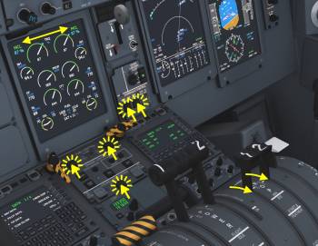
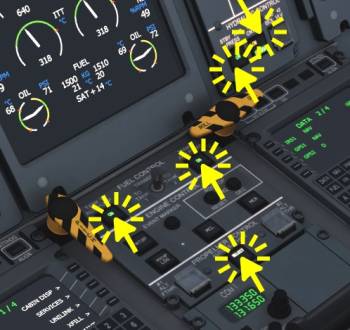
- Click the Auto-Feather button in front of the power levers to ARM the auto feather system
- Click the STBY HYD PRESS and PTU CONTROL buttons to set them ON
- Click the TANK 1&2 AUX PUMP buttons to set them ON
In the most left column of the overhead panel set the following switches:
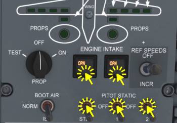
- PITOT STATIC 1, 2 and STBY all ON
- BOOT AIR (NORM/ISE) to ISO
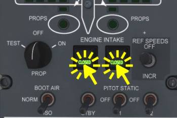
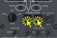
- Click the ENGINE INTAKE buttons left and right once. Wait for them to display “OPN”
Note - The engine intakes are opened so that foreign object debris (FOD) or precipitation (e.g. hail) bypasses the main intake and it not sucked into the compress or of the engine. When ever the aircraft is at an altitude where debris or even birds can be an issue or the precipitation is heavy or the runways are contaminated the intake flaps should be opened. Above thermal tops (cumulus cloud tops) there typically aren't any birds and debris can't be be thrown any higher than this by updrafts either.
On the most right column of the overhead:
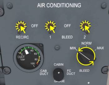
- Click the RECIRCling fan to ON
- Click engine 1 and 2 BLEEDs to ON
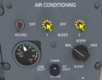
- Scroll over the BLEED flow selector to select MINimal bleed air flow. This reduced the power reduction for the engines during takeoff. After the initial climb this knob can be reset to NORM.
Flight Control Check (Optional)
- Set the STEERING switch in front of the tiller (left side of pilot seat) to OFF
- Set the CONTROL LOCK to OFF
- Test all flight controls free and correct (indicating on lower half of the MFD)
- Set HYD #3 ISOL VLV to ON
- Test elevator and aileron
- Set HYD #3 ISOL VLV to OFF
- Set the CONTROL LOCK to ON
- Set the STEERING switch to ON
| Before Taxi Checklist | |||||
|---|---|---|---|---|---|
| No. | Location | Panel Name | Action | Remarks | |
| 1 | Pedestal | Throttle Quadrant | PROP LEVER 1&2 | MAX 1020 | |
| 2 | Pedestal | TRIM | ELEV., AIL., RUDDER | SET 3x | Rudder slight right |
| 3 | Overhead | AIR CONDITIONING | BLEEDS | ON/MIN | |
| 4 | Pedestal | PROPELLER CONTROL | AUTOFEATHER | SELECT | |
| 5 | Pedestal | Throttle Quadrant | FLAPS | FLAP 5° | |
| 6 | Pedestal | FUEL CONTROL | TANK 1&2 AUX PUMP | ON | |
| 7 | Front Panel | HYDRAULICS | STBY HYD PRESS | ON | |
| 8 | Front Panel | HYDRAULICS | PTU CTRL | ON | |
| 9 | Pilot Panel | Switching Panel | STEERING | ON | |
| 10 | Pedestal | Throttle Quadrant | CONTROL LOCK | ON | |
| 11 | Overhead | ICE PROTECTION | ENGINE INTAKE 1&2 | SET OPN | Press each button 1x |
| 12 | Overhead | ICE PROTECTION | PITOT STATIC | ON 3x | * |
| 13 | Overhead | ICE PROTECTION | PITOT STATIC ISOLATION VALVE | ON (ISO) | |
| 14 | Glareshield | Right side | ANTI SKID | ON | * |
During Taxi
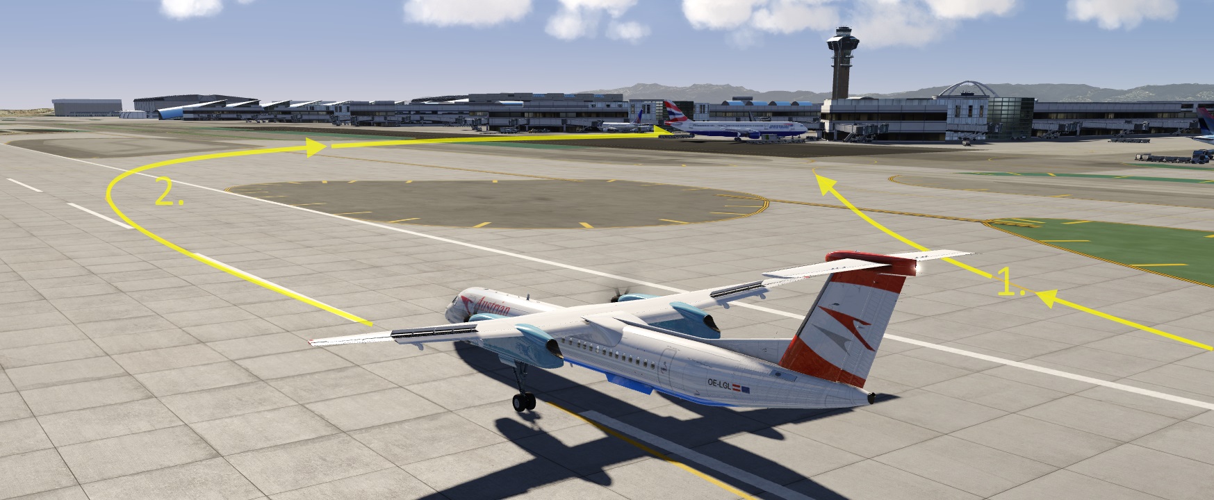
Release parking brake advance the power lever to start moving. Start taxiing to runway 27.
Preparing The Engine
We already set the condition levers to MAX 1020 and we won't move them until we're in the climb. We select the engine rating “RDC TOP TRQ” with 4% power decrease for this tutorial. If your runway is short you may want to use full takeoff power, in this case press the MTOP button before takeoff.
On the ENGINE and PROPELLER CONTROL panel in front of the throttle quadrant
- Click the “DEC” button on the RDC TOP two times now
- Click the AUTOFEATHER button to arm the system
Arming Ground Spoilers
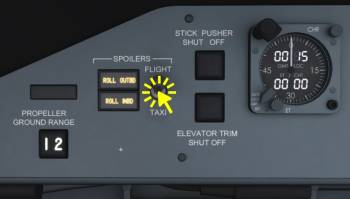
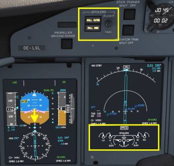
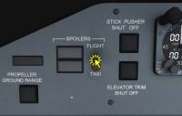
On the glareshield, click the SPOILER switch to FLIGHT. Monitor spoiler extension on the MFD with your power levers at IDLE.
Note - it is very common to see Q400s waiting for takeoff with their spoilers extended. They will retract as soon as takeoff power is set and during landing they extend again once the power lever angle is low enough.
Also on the glareshield:
- Click the YD push button on the autopilot panel (FGCP) so that the two arrows light up. This enables the yaw damper.
Takeoff Configuration Test
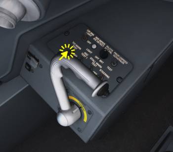
Now, if we didn't forget anything the aircraft should be in a condition that we can take off with. To test that we use the takeoff configuration test which is located in front of the tiller and may be hidden by it.
- Click the switch to the on position
- Listen if an audible warning can be heard, if it does we have forgotten something. This could be either flaps not between 5 to 15°, condition levers not at MAX 1020 RPM or the steering tiller is still deflected.
- Click the switch again to set it to the off position (this will also mute the warning if it was present)
When no warning could be heard the aircraft is ready to go.
| Taxiing Checklist | |||||
|---|---|---|---|---|---|
| No. | Location | Panel Name | Action | Remarks | |
| 1 | FLT-CTL | Pedals | BRAKES | TESTED | |
| 4 | Glareshield | Autopilot | YD (YAW DAMPER) | ON | |
| 5 | Glareshield | Autopilot | CHECK MODES | HDG SEL, GA, ALT SEL | |
| 2 | Pilot Panel | Switching Panel | T/O WARN TEST | ON then OFF | No audible warning should sound |
| 3 | Pedestal | WEATHER RADAR | MODE | ON | |
| 4 | Pedestal | ARCDU | ATC/TCAS | ON ALT | Hold down the lower right line select button |
Entering The Runway
After receiving takeoff clearance by ATC we're cleared onto the runway. Taxi onto the runway and line up with the center line.
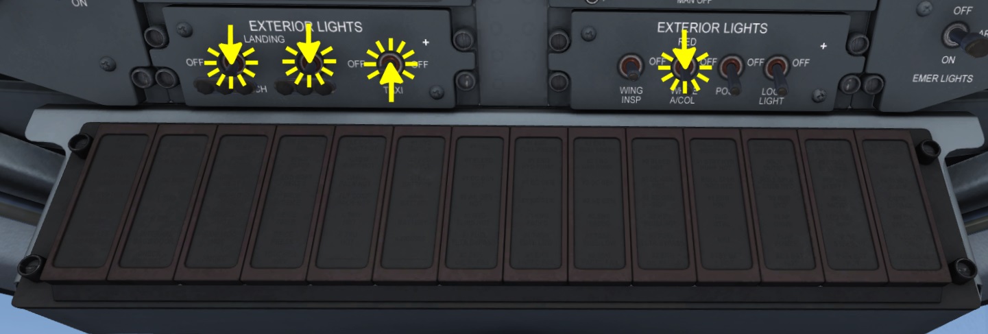
- Click the LANDING and FLARE light switches to set them ON (forward position)
- Click the TAXI light switch to turn off the taxi light
- Click the A/COL (anti collision light) 2x ore rotate your mouse wheel over it to set the anti-collision lights to WHITE
- Whilst doing this look at the caution and warning panel to check if it is blank, as seen in the screenshot
- For this tutorial we're using BLEEDS OFF. Click the BLEED 1 and BLEED 2 switches to OFF (upper position)
Remove the control lock by clicking on the black bar in front of the power levers again. Have a quick scan of the PFD and to check if the flight mode annunciator (top section of the PFD) is indicating either no modes what soever or WING LVL or HDG SEL as lateral mode and GA as vertical mode, ALT SEL armed in white.
We have now reached the takeoff configuration. When you set the aircraft onto the runway using the location dialog in the main menu almost all the steps above will be completed already.
| Runway Entry Procedure | |||||
|---|---|---|---|---|---|
| No. | Location | Panel Name | Action | Remarks | |
| 1 | Pedestal | Throttle Quadrant | CONTROL LOCK | OFF | * |
| 2 | Overhead | EXTERNAL LIGHTS | ANTI COLLISION | ON WHITE | |
| 3 | Overhead | EXTERNAL LIGHTS | LANDING | ON | |
| 4 | Overhead | EXTERNAL LIGHTS | FLARE | ON | |
| 4 | Overhead | EXTERNAL LIGHTS | TAXI | OFF | |
| 5 | Overhead | AIR CONDITIONING | BLEEDS | AS REQUIRED | ON/MIN or OFF |
| 6 | Front Panel | PFD | CHECK AFCS MODES: HDG SEL, GA + ALT SEL | SET/CHECKED | HDG 273° set, flight director visible and shows 9 deg pitch |
| 8 | Overhead | Caution Panel | NO WARNING | CHECKED | |
Takeoff
The next part will be quite stressful and there is a lot to do in a brief period of time. Before attempting this read this section completely or pause your simulation if you try to follow it step by step. With practice the takeoff will get easier. At the beginning we're going to summarize the actions we will perform in a second.
- Apply full power
- Keep aircraft on center line
- Rotate at VR
- Gear up
- Fly the aircraft: Stabilize pitch attitude and speed to about V2 + 10kts, maintain runway heading
- Engage autopilot and correct pitch if needed with vertical wheel
- Engage LNAV at 400ft
- First turn flown by autopilot at 1000ft
- At 1500ft select IAS with 210kts
- Retract flaps
Let's get going.
Set Takeoff Power
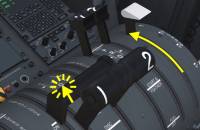
- Hold the brakes and move your throttle to about 50% until the spoilers retract (yellow lights in front of you goint out).
- Monitor both engines and props to see if they spool up identically.
- Let them stabilize until they reached the similar values for torque, propeller RPM (NP) as well as high pressure rotation speed (NH). Usually they spool up almost identically and you don't have to wait at all.
- Release the brakes and advance your throttle levers fully forward (rating detent) to set the pre-selected takeoff power.
Stay On Centerline, Rotate
Maintain the aircraft on the center line using the rudder. When the airspeed on the PFD reaches VR (VR is removed from the V-Speed legend on the speed tape) ease the nose up gently and rotate with about 3° of pitch per second.
Positive Rate, Gear Up
Once the vertical speed indicator indicates a positive climb rate and your radar altimeter confirms this by increasing values, select the gear up!
- Click the landing gear lever or use your key or button assignment. Typically this is the “g” key on your keyboard.
- Fly a speed about 10kts above V2 (indicated as -V2 on the PFD speed tape)
Correct The Attitude, Fly The Aircraft
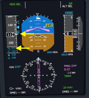
Try to hold the wings level and correct for any heading deviation, use only a slight bank angle (5°) to turn back onto the selected (runway) heading to fly a straight first segment. If you look closely on the screenshot above our heading has already deviated a few degrees to the left. We can follow the flight director bank commands which indicates a slight correction to the right is needed.
Note - Use rudder trim to trim away any side slip. With the 8 right clicks of rudder trim prior to takeoff the slip angle should be quite low but depending on power you might want to add a bit more to keep the aircraft flying straight.
Stabilized, Autopilot On
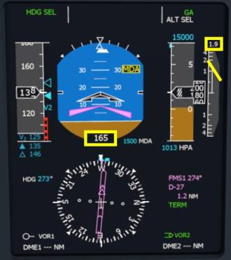
Above roughly 50ft the autopilot can be turned on. We'd recommend stabilizing the attitude first and also stabilize the speed at around V2 + 10kts (135 to 140kts in this case) at which point the trend arrow on the speed tape of the PFD will disappear. Now, if you want to, engage the autopilot. The autopilot will switch to PITCH HOLD mode which can be seen on the top right of the PFD (highlighted in the screenshot above). Use the vertical wheel in the center of the autopilot panel to change the current pitch necessary.
- Engage the autopilot by clicking the “AP” master on the autopilot panel (FGCP) or use your key/button assignment. Default key is “a”.
- Scroll with the mouse wheel over the vertical wheel in the center of the autopilot. Scrolling up (finger moving upwards) will lower the nose of the aircraft and allow speed to increase. Similarly a scroll down motion over the vertical wheel increases the pitch attitude and slows the aircraft down.
- Monitor the indicated speed and correct the selected pitch if necessary.
Engage Lateral Navigation (LNAV)
- At roughly 400ft above the ground click the “NAV” button on the Flight Guidance Control Panel (FGCP) (autopilot panel). “LNAV” should be displayed on the top left corner of the primary flight display since we are still very close to the flight plan.
Note - At around a thousand feet the flight plan will take the first turn, don't be surprised.
Acceleration Phase
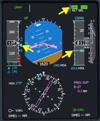
Right after passing the MDA marker at 1500ft we are going to change the vertical mode of the autopilot to IAS hold.
- Click the “IAS” button on the FGCP
- Use the mouse wheel over the vertical wheel in the center of the FGCP to increase the speed to 210kts, use a nose down input (finger scrolling upwards and the aircraft following the rotation of the mouse wheel)
After performing these actions the primary flight display (PFD) should look as shown in the screenshot below. The autopilot is flying, LNAV is turning us right on course, we passed the 1500ft above airport elevation, our radar altimeter confirms this (1620ft indicating), speed is nice and stable, without a long trend arrow, vertical speed is good.
Flap Retraction
Once we are above to MDA marker and above the speed for flap retraction (V FRI), which is displayed as a solid cyan triangle on the speed tape, as displayed in the screenshot above, we are safe to retract the flaps.
- Use either your assigned key or button commands (e.g. Shift+F) or move your mouse cursor over the white flap handle and rotate the mouse wheel or drag the flap lever with the left mouse button held down.
The only thing left to do at this point, which we will have to monitor for the entire flight, is align the selected heading bug with our current heading.
We have now mastered the most difficult part of the entire flight, congratulations!
After Takeoff
We have already retracted the landing gear and flaps, now we will reduce the power for climb.
- Set climb power by reducing the condition levers to 900. You can drag both levers at the same time by holding down the right mouse button and then moving the mouse slowly. Watch how the engine rating changes to MCL (Maximum CLimb power)
- Re-trim the aircraft with rudder trim
And then, finally, we're cleaning up the aircraft after the takeoff.
- Click the STBY HYD PRESS button to set it to off and repeat that for PTU CTRL button right next to it.
- Click the TANK 1 AUX PUMP and TANK 2 AUX PUMP below the engine display to OFF.
- Click the AUTOFEATHER push button on the PROPELLER CONTROL panel
| After Takeoff Checklist | |||||
|---|---|---|---|---|---|
| No. | Location | Panel Name | Action | Remarks | |
| 1 | Front Panel | LANDING GEAR | LANDING GEAR | UP | |
| 2 | Pedestal | Throttle Quadrant | FLAPS | ZERO | Above V-FRI |
| 3 | Pedestal | Throttle Quadrant | PROP LEVER 1&2 | 900 | |
| 4 | Overhead | AIR CONDITIONING | BLEEDS | ON/NORM | |
| 5 | Front Panel | HYDRAULICS | STBY HYD PRESS | OFF | |
| 6 | Front Panel | HYDRAULICS | PTU CTRL | OFF | |
| 7 | Pedestal | PROPELLER CONTROL | AUTOFEATHER | OFF | |
| 8 | Pedestal | FUEL CONTROL | TANK 1&2 AUX PUMP | OFF | |
Climb
The flight plan is going to to a couple of slight turns now and only two and a half minutes into the flight we will already pass the San Diego VOR (“SAN”) on our route. from there on out we just climb straight and follow the coast to the north.
Close Engine Intake Bypass, Release Passengers
Once we passed the cumulus cloud tops it is safe to assume that there won't be any turbulence. Depending on the weather settings the turbulence might be slight enough to release the passengers from their seat. Our tutorial flight is so short that they only have a couple minutes anyway. We can then also close the engine intake flaps since it's unlikely we will encounter any birds or other debris.
10,000ft, Lights Off
At 10,000ft we turn off the lights and release the passengers.
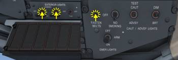
- Click the APPROACH and FLARE ligth switches in the overhead panel
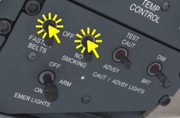
- Use the mouse wheel to set the FASTEN BELTS switch to off.
Above transition altitude (18,000ft in USA, about 5,000ft in Europe) push the BARO SET knob left of the PFD. This will set the pressure to 1013 hPa or 29.92 InHg (which at the current development state it already is). In this tutorial this won't be necessary as we are flying in the USA but stay below the 18 thousand feet anyway.
| Climb Checklist | |||||
|---|---|---|---|---|---|
| No. | Location | Panel Name | Action | Remarks | |
| 1 | Overhead | Signs | FASTEN BELTS | AS REQUIRED | |
| 2 | Front Panel | PFD | ALTIMETERS | SET STD | Above transition altitude |
| 3 | Overhead | EXTERNAL LIGHTS | LANDING | OFF | Above 10,000 ft |
| 4 | Overhead | EXTERNAL LIGHTS | FLARE | OFF | Above 10,000 ft |
| 5 | Overhead | ICE PROTECTION | ENGINE INTAKE 1&2 | SET CLOSED | Above cumulus cloud tops |
Cruise
Upon reaching cruise altitude the autopilot will start to nose forward and capture the selected altitude (because we manually armed ALT SEL before). The altitude capture is indicated by ALT* on the top right corner, followed by ALT once captured. At this point the aircraft will start accelerating.
- Using your mouse wheel set the PROP levers to 850. The engines will now be in MCR (Max CRuise rating)
- Reduce the throttle position to maintain a speed of about 260 kts, roughly 68% torque is good.
Descent Preparation
In this short hop from San Diego to Los Angeles the cruise will be very short. After the turn at NFG it's already time to think about the descent. (Don't forget to synchronize the heading after the turn…). So let us plan ahead and prepare the descent and approach into the destination airport now.
Approach Briefing
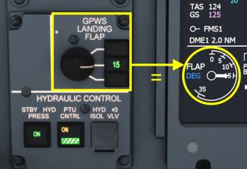
We're heading into KLAX which has a field elevation of 124ft. We planned to fly a direct entry to the ILS approach for runway 25R, the ILS frequency is 111.10 MHz and the Course is 250°, both of which will be tuned automatically by the FMS since the ARCDU mode selectors are set in the FMS position. Decision height is 120ft which is CAT II and we're using the autopilot and FD DUAL down to minimums and land manually, as always in the Q400. We're going to use flap 15 for landing that gives us a Vref of 122kts.
We can descent down to roughly 2500ft above the destination airport elevation. For KLAX this would mean around 2620 feet. We're going to round that up a little bit because we want to have more time on the final approach so we're using 3000ft in this tutorial. Anything between 2500ft and 3000ft would be good here if you plan to repeat the flight. The lower the altitude you select the less time you have to prepare the aircraft and you will need more aggressive corrections down low. If you stay up near the glide slope (roughly 3000ft above the airport at the final turn) and slow down in time it will be quite a relaxed approach.
Arming VNAV
We're letting the autopilot and FMS figure out when we need to descent and will use the vertical navigation (VNAV) functionality for this in this tutorial. In the real world VNAV isn't used that often, typically ATC has other plans for us so we have to fall back to indicated airspeed hild (IAS) or vertical speed (VS) hold.
- Select the FMS1 as navigation source (already done)
- Mouse over the altitude knob (ALT) on the Flight Guidance Control Panel (FGCP) and rotate the mouse wheel to set a selected altitude of 3000ft
- Click the ALT SEL pushbutton
- Click the “VNAV” pushbutton.
Now that we know the autopilot will start to descent on its own we can do other tasks. When the Top Of Descent (TOD) on the navigation display (small white circle with a <TOD> label) comes really close to the aircraft symbol we have to monitor the flight mode annunciator (FMA) on the PFD (upper part of the display). Once VNAV PATH engages we have to reduce the power or we will speed up dramatically. Remember to stay at or above FLT IDLE during the entire flight. Other wise the loud beta warning horn (oioioioioiou) will ring. Try to maintain 240kts during the descent, you're going to need a little bit of power for this. Don't forget to retrim the rudder after the power change.
Pressurization
The cabin pressurization system, though not actually modeled yet (4th August 2017), needs to know the landing altitude to schedule the cabin rate correctly.
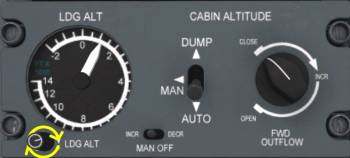
- Move your mouse cursor over the small knob in the lower left corner of the pressurization system (can be found in the overhead panel)
- Rotate the knob with your mouse wheel until the needle displays roughly 120ft.
V-REF
For our own reference we're going to set the solid cyan triangle to the approach reference speed. We can fly this speed in the final approach and use it as a guide/reference for our power management. During the approach we want our airspeed to stay at or above V-REF.
- Click the “SEL” button left of the PFD to select the speed with the solid triangle (usually V FRI)
- Use the speed bug knob right next to it to adjust the speed within 5 seconds after pressing the button
Decision Height
The final step for the approach preparation is to set the decision height (DH). We're going to use a fantasy 120ft category 2 height. In the ILS approach we are not allowed to descent below this height above ground if we don't have the runway in sight. If we don't see at least the approach lights of the runway though the thick fog we have to go around and the missed approach procedure. But we chose clear weather for this flight so this won't be an issue. If we look outside the windows we can already see L.A.
- Rotate the outer knob of the DH/MDA selector to DH (left click the outer ring)
- Mouse over the inner knob and scroll up to change the DH value on the PFD to 120ft.
- Repeat for the right side PFD as well!
VNAV Capturing
With the VNAV descent armed and close to the <TOD> on the navigation display the vertical deviation is displayed to the right of the attitude and left of the altitude tape on the PFD (see screenshot above). The magenta line indicates the correction required to stay on the vertical profile. At fist the path is above us and parked at the upper end of the scale, then it moves down and VNAV engages at the Top Of Descent (<TOD>). After that we reduce power and aim for 240kts in the descent.
Note - Don't reduce the throttle too much because the Q400 doesn't like a power lever angle below FLT IDLE, as mentioned above. And the huge Props on this aircraft act like airbrakes, keep the power up until touch down or you really start to slow down and drop like a rock (well almost but you get the point). For the descent we used about 28% torque during the descent but this might change with next versions.
| Descent Preparation Checklist | |||||
|---|---|---|---|---|---|
| No. | Location | Panel Name | Action | Remarks | |
| 1 | Overhead | PRESSURIZATION | LANDING ALTITUDE | FIELD ELEV. SET | KLAX is at 124ft |
| 2 | Front Panel | GPWS | LANDING FLAP | AS REQUIRED | We're going to use flap 15 for this tutorial, no action required |
| 3 | Front Panel | PFDs (left and right) | V-SPEEDS | SET | set 122kts for flap 15 and current mass |
| 4 | Front Panel | PFDs (left and right) | DH/MDA | SET | DH 120ft in this tutorial |
Descent
Monitor Speed
Once the autopilot pitched down the nose to initiate the descent we have to watch the speed of the aircraft even closer. With decreasing altitude the maximum airspeed will decrease below roughly 10,000ft. The red band on the speed tape will begin to come dow, if we have to stay below 240kts we should be good. For some extra safety and protection against bird damage (not yet simulated) we will keep the speed at least 10kts below maximum operating speed (VMO).
Transition Level
Descending though the transition level we have to change from the flight levels and standard pressure back to local airport conditions (QNH). Since the current weather engine of the Aerofly doesn't change the atmospheric pressure and we stayed below the transition altitude of 18,000ft in USA in our tutorial flight, there is nothing to do. If pressure were modeled all you need to do in the Q400 is rotate the BARO SET knob to the left of the PFD with the mouse wheel. Repeat this in a similar fashion for the first officers side as well the standby instrument.
Reaching Cumulus Cloud Tops
- Reduce speed to roughly 230kts. Below the clouds we may encounter birds or debris (not modeled yet) and at high speeds the damage those objects make is significant.
- Open the engine intake flaps by clicking on the two pushbuttons in the overhead ice protection panel. They will display OPN after a brief period of time once they are fully open.
10,000ft Checks
- Turn on the Seat belt signs in the overhead by clicking on the switch.
- If not already in the ON position also click the NO SMOKING switch.
- Click on the switches for the APPROACH and FLARE landing lights to set them ON (forward position)
Checks Before The Approach
We're descending to our destination airport and are only about 7000ft high at this point. On the Navigation Display page (ND) of the Multi Function Display (MFD) we can see the last waypoint coming into view at roughly 15 NM, time to prepare the approach.
- Synchronize the selected heading with the current heading on the ND (value is displayed at the top of the arc). Do do so please move your mouse cursor over the heading bug and use the scroll wheel, as shown earlier.
- Monitor speed, we should have a margin of at least 10 kts to the red overspeed tape
- ALT SEL is armed in white, so the autopilot will capture the aircraft once we reach the selected 3000ft.
- Both PFDs have 120ft DH set
- Rudder trim is set (side slip on PFD shows zero)
| Descent Checklist | |||||
|---|---|---|---|---|---|
| No. | Location | Panel Name | Action | Remarks | |
| 1 | Front Panel | PFD P&FO | ALTIMETERS | SET LOCAL QNH | Below transition level |
| 2 | Overhead | Signs | FASTEN BELTS | SET ON | No later than 10,000ft |
| 3 | Overhead | EXTERNAL LIGHTS | APPROACH | ON | Below 10,000 ft |
| 4 | Overhead | EXTERNAL LIGHTS | FLARE | ON | Below 10,000 ft |
| 5 | Overhead | ICE PROTECTION | ENGINE INTAKE 1&2 | SET OPN | Below cumulus cloud tops |
Approach
Since the last turn of our flight from San Diego to Los Angeles Intl. is approaching rapidly we should begin to prepare the approach and arm the localizer and glide slope capture.
Preparing The Right PFD
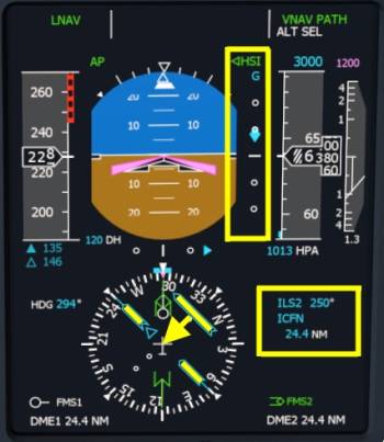
- On the right side PFD switch the navigation source to NAV2 (“ILS2”) and check if we are receiving the ILS signal. For our tutorial flight the PFD should show “ICFN” on the legend to the right of the display, the course of 250° should be set automatically.
With the ILS2 selected on the right side PFD the display should look similarly to the screenshot below. To the right of the PFD we see the selected NAV SOURCE which we set to ILS2. Course has been set by the autotuning to 250° which should be correct for the ILS 25R into KLAX.
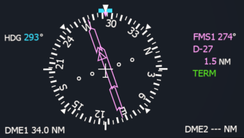
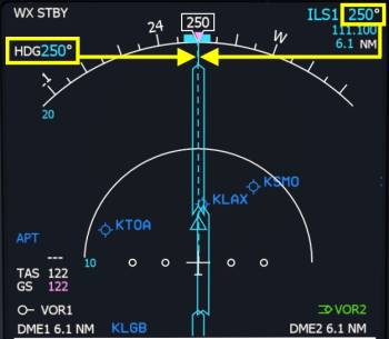
The HSI on the bottom center shows the localizer deflection. We're heading to roughly 294° and the localizer and runway course are about 250°, so roughly a 45° intercept. As we come closer to the localizer the course deviation indicator will move towards the center as shown with the arrow.
To the right of the attitude you find your typical glide slope diamond, currently indicating that we are slightly below the 3° ILS glide.
Preparing PFD On Left Side
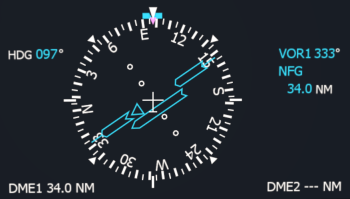
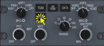
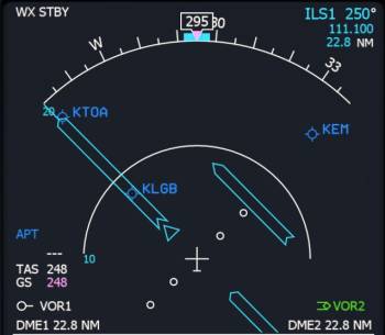
To confirm we receive the ILS on our side as well (NAV1 receiver) we can use a little trick in the Q400. We have the option to display the localizer deflection on our MFD. To so so we have to hold down the “FORMAT” button on the EFIS control panel for one second (in the real world aircraft), due to technical reasons we used the right mouse button for this.
- Look down and right to the EFIS Control Panel (forward and left of the throttle quadrant)
- Hold down the FORMAT button on that panel for one second
As you can see on the screenshot we can see the deflection of the NAV1 receiver, currently tuned into 111.10 MHz (ILS1) and set to the course of 250°, displayed in the top right corner. This confirms we have the ILS tuned correctly and can use it in a second.
To leave this view and return to the map mode either
- Hold down the FORMAT button for one second again
- Click the FORMAT button (due to a bug 2x currently)
Heading Select And Vertical Speed
To intercept the localizer smoothly we're going to use the HDG SEL function and Vertical Speed (VS) with our current heading and a vertical speed of -1000ft/min. Keep your torque at roughly 23% for now to help us slow down gently. Don't let the speed drop too much at this point, we don't want to waste our time here. With 200 to 220 kts you're doing just fine for now.
- Click the “VS” pushbutton on the Flight Guidance Control Panel (FGCP)
- Use the vertical wheel in the center of the panel to adjust the VS to -1000 ft/min (probably nose up input needed)
- Click the “HDG” pushbutton on the FGCP to engage HDG SEL
- Alternatively to HDG SEL: Click the NAV button to deselect the current nav mode “LNAV”. Since we are wings level this will put us directly in HDG HOLD.
Arm Localizer Capture
- With the HSI SEL pointer pointing to the left (as throughout this flight) now rotate the left NAV SOURCE knob with your mouse wheel to select NAV1 (“ILS1”) as a navigation source on the left PFD.
- Click the approach button (APPR) on the FGCP
Note - The left PFD should now display in the flight mode annunciator (FMA): HDG SEL, LOC (white) and VS -1000, ALT SEL (white) and GS (white). The Glide Slope (GS) can only engage when the localizer is already in capturing mode (LOC*) or localizer track (LOC). During testing the “ALT SEL” usually captured first and the vertical mode changed from VS to ALT* (altitude acquire) followed by ALT (altitude hold). This is not a big problem as GS will remain armed in white and capture the glide slope (GS*) as soon as possible.
Approach Checklist
Whilst the autopilot could be capturing the glide slope, let us quickly do a few remaining items on the to-do list.
On the hydraulics panel just below the gear lever
- Click the PTU CTRL button to ON
- Click the STBY HYD PRESS button right next to it to ON
Below the engine display and in front of the throttle quadrant:
- Click the TANK 1 AUX PUMP and TANK 2 AUX PUMP pushbuttons
- Click the AUTOFEATHER pushbotton (usually done later but before we forget…)
| Approach Checklist | |||||
|---|---|---|---|---|---|
| No. | Location | Panel Name | Action | Remarks | |
| 1 | Pedestal | FUEL CONTROL | TANK 1&2 AUX PUMP | ON | |
| 2 | Front Panel | HYDRAULICS | STBY HYD PRESS | ON | |
| 3 | Front Panel | HYDRAULICS | PTU CTRL | ON | |
Landing
Localizer Capture
The autopilot switches to LOC* and starts turning to the left to establish the aircraft on the localizer. The glide slope will be captured shortly after that.
Synchronize the selected heading
In case of a go around we would want to have a good reference to maintain runway heading.
- Mouse over the selected heading knob on the FGCP and use your mouse wheel to adjust the selected heading to the localizer course (250°).
Reduce Speed
Once the needle of the localizer starts moving we know that we are about to do the last turn and since the glide slope is also already off it's maximum deflection it's time for us to reduce speed further. Since the altitude captured and we didn't increase power the speed is already dropping a bit. Let it drop to about 180 kts. Once the glide slope captures you need to reduce power. Set FLT IDLE if speed is getting away.
Note - Don't move the power levers below FLT IDLE in the entire flight, unless you want to hear the full beauty of the beta warning horn that goes like this “WioWioWio”.
Flaps 5 Degrees
When the aircraft levels out onto the ILS course the glide slope should engage any second. We should be below 200kts, select flaps 5°. Use your assigned key or button commands (e.g. “f” key) or your mouse wheel over the flaps lever. (I think you will find the white lever now, we have used it before for the takeoff.) Continue slowing down to 160 kts.
Set Reduced NP Landing
During the approach and landing want a low propeller speed (850 RPM) since the setting MAX 1020 RPM is quite loud. But for a go-around we want full power available and that is only possible with 1020 RPM since power = torque * rotation speed. To achieve both we have the clever option of latching the propeller rotation speed (NP) at 850 RPM with our PROP levers already at MAX 1020. When we increase the power levers above roughly 50% the latch is removed and the propeller speed increases to 1020 automatically.
To achieve this condition:
- Move the PROP levers to 850 RPM if not already in that position from cruise and descent.
- Click the RDC NP LDG pushbutton
- Within 15 seconds move the PROP levers to MAX 1020 RPM and make sure to keep your the throttle inputs below 50% for the rest of the flight.
Note - To cancel this state either increase power above 50% to perform a go around or push the RDC NP LDG pushbutton a second time or move the condition levers again.
Gear Down, Flaps 10
At around 2000ft radar altitude (RA) (displayed on the PFD at the bottom of the attitude indicator, small white text on black background) we're selecting gear down. When speed is below 181kts we can also extend the flaps to 10 degrees. Increase power now, we added a lot of drag, we want to keep the speed at 145 or so.
Note - The Q400 is equipped with a gear warning horn. If the gear is not down and the aircraft things it should be (e.g. power lever low and RA low) then a constant warning horn will sound. “BEEEP”
Retrim the rudder so that the side slip is zero. This also helps the localizer tracking by the autopilot.
Landing Flap 15
At around 1500ft RA set flaps to 15 (check that speed is below 172kts), which is our final stage of flaps for the very long runway in L.A. we could even land with flaps 10 if we wanted but we want to try get off the runway quickly as well, since we're going to park near the middle of the terminal.
Maintain a speed of around 135 kts now. The final approach reference speed (V-REF), as mentioned and set as V-Speed before, is around 122kts in this configuration. Time to run the landing checklist.
Note - If you want to be even more realistic for this landing and use flaps 10 or want to test out flaps 35 remember to adjust the GPWS LANDING FLAP knob. The Ground Proximity Warning System (GPWS) will otherwise warn you about your flap configuration on short final. This alert is currently not modeled (20th August 2018) but might be in the future.
Bleeds
When speed is stabilized look up to the overhead panel and set the bleed strength to MIN. This increases engine performance which we would need in case of a go-around. In L.A. the go-around is not difficult, there are not mountains near the airport that we would have to climb over. In front of us is just the Pacific Ocean, so we can leave the engine bleeds on but we're going to reduce the demand by setting the strength to MIN.
- On the AIR CONDITIONING panel in the overhead, top right, mouse over the knob and use your mouse wheel to scroll it to “MIN”. You could also use your left mouse button to turn it left to MIN.
| Landing Checklist | |||||
|---|---|---|---|---|---|
| No. | Location | Panel Name | Action | Remarks | |
| 1 | Front Panel | LANDING GEAR | LANDING GEAR | DOWN 3 GREEN | |
| 2 | Pedestal | Throttle Quadrant | PROP LEVER 1&2 | MAX 1020 | |
| 3 | Pedestal | Throttle Quadrant | FLAPS | SET/INDICATING | Select 15° and verify position |
| 4 | Overhead | AIR CONDITIONING | BLEEDS | ON/MIN | |
1200ft RA, DUAL FD
With the ILS1 and ILS2 set to the same frequency, same course and good signal, ILS1 and ILS2 selected as navigation sources and LOC and GS captured the PFDs will show “DUAL FD” up and right of the attitude indicator. The HSI SEL button on the Flight Guidance Control Panel (FGCP) points left and right indicating that the autopilot is using both navigation receivers. In case one LOC or GS is lost on either PFD the HSI will switch to the remaining good side to keep the approach.
Additional requirements for the category 2 ILS approach with this DUAL FD mode are two identical decision heights on left and right PFD, both below 200ft (CAT 2) and, of course, working radar altimeters.
This DUAL FD fail→active, fail→passive behavior is modeled in the Aerofly FS Q400, if you re-tune one receiver for example or switch the nav source on one side away from ILS. In case the capability of the aircraft to fly the ILS 2 approach drops (e.g. one nav source is set to the wrong position) a CAT 2 FAIL message is displayed. Then your approach minimums change and you might need to go around.
1000ft RA, Reduce To Final Approach Speed
At 1000ft slowly reduce the speed to V-REF (122kts), use only small power adjustments. Perform final touches to the rudder trim. Enjoy the ride, we're not going to do anything until we reach the decision height of 120ft.
120ft RA, Decision Height
At this point we have to decide if we have the runway or runway approach lights in sight to be able to continue the approach visually. We have very good weather, so no need to go around at this point for that reason. If your speed isn't stable between 122 (VREF) and 132kts (VREF + 10kts) you might want to consider going around.
We have to disconnect the autopilot at this point anyway, if you think you can manage the landing continue, if it looks chaotic go around.
To disconnect the autopilot you can do several things.
- Intended way: Use the autopilot disengage button or key as set in your control assignments
- You can also press the autopilot master key or button (default key “a”)
- Last option, which isn't really good that close to the runway, move your mouse over to the autopilot panel in the virtual cockpit and click the “AP” button. Depending on your current view you might need to pan the camera to see the button, not ideal! Using a button is recommended here.
Flare, Keep Power In!
Different to a lot of other aircraft you mustn't pull power back to FLT IDLE or even DISC (your throttle at idle). The large props of this aircraft accelerate the air and push it onto the wing. Therefor the wing sees a faster airspeed behind the propeller and is also creating more lift. If you pull the power lever to FLT IDLE at this point the props will actually slow the air and act a bit like wind mills. Not only does the drag increase dramatically also your lift decreases a lot, and you fall from the sky and have a hard landing.
Instead, keep your approach power (roughly 20%) during the entire flare, until the aircraft has settled down.
Touch Down, Now Idle
With the main gear on the ground pull your throttle lever all the way back to idle. This moves the power levers to DISC in the simulator and the propellers are pitched to 0° flat. In this position they help us slowing the aircraft without needing too much brakes actually. With the power at idle the ground spoilers also extend and help to dump the remaining lift. This increases the down force and thus breaking action and also adds a little bit of aerodynamic drag.
On a short runway you can also use reverse thrust where the prop is pitches backwards and actively pushes air forward. This is pretty loud in the real world and it also can cause small stones to be thrown forward and damage the props or antennas in the forward section. In short: Shouldn't be done on a regular basis but this is a sim, right? No small stones simulated yet and where is the fun if you can't use full reverse and try to do the shortest landing possible…
Note - Due to an imperfection in the current governor you will need to tap the reverser key or button once or move your axis in the reverse ever so slightly. This will make the prop flip to DISC and give you a much better braking force.
Braking
Use your pedals or, if you don't have any, use your assigned brake key or button (default key “b”). Touch the brakes gently, don't hold full brakes as this would be quite unrealistic and would typically only be done on short runways or emergencies. Real aircraft would need maintenance a lot more often due to brake wear…
Try to take the second high speed exit off the runway to the right. (The one after a small concrete patch to the right of the runway, ending directly behind that parked British Airways aircraft). This should take only slight to moderate braking and we'll end up right in front of the terminal where we want to park.
With the little trick (tapping the reverser key once) we could turn off the second exit whilst testing without braking at all in our testing with the current version of the Aerofly FS.
Lights Off
Do a quick look up to the EXTERNAL LIGHTS panel in the overhead and turn off the APPROACH and FLARE landing lights. Set taxi lights to ON.
- Click the APPROACH and FLARE light switch to OFF
- Click the TAXI light switch to set them on.
- Mouse over the Anti Collision Light (A/COL) switch and rotate the mouse wheel to set it to RED
Exit Runway
Slow down on the taxi way leading and can keep the speed moderately high (35kts when exiting). When you exit the runway (passing over the hold short lines) your speed should be below 20kts again.
After Landing
Now that we have crossed the hold short line completely we may stop and clear up the aircraft after landing. We have already set off the landing lights so no one will be blinded by them on the ground.
Flight Director Clear, Yaw Damper Off
- Click the flight director standby (STBY) button to remove all current modes and the flight directors from the PFDs
- Click the yaw damper button (YD) to set the yaw damper to off
Spoilers To Taxi
- Click the SPOILERS FLIGHT/TAXI switch to the down position to disarm the ground spoilers. As a result the spoiler lights next to the switch will go out and the MFD shows spoilers in down position.
Close Engine Intake
- Click each engine intake button in the overhead, ICE PROTECTION panel to close the bypass doors.
Flaps Up, Control Lock On
- Click the control lock to engage it. This will prevent wind gusts from deflecting the ailerons and also limits the power demand on the ground up to a certain point.
- Mouse over the flap handle and scroll up to set the flaps up or use the key command “Shift+F” three times.
Fuel Pumps Off
On the FUEL CONTROL panel (below the engine display):
- Click TANK 1 AUX PUMP to off
- Repeat for TANK 2 AUX PUMP
Transponder Standby, Weather Radar Standby
- Hold down the lower right line select of the ARCDU1 for one second. This sets the ATC/TCAS to standby (SBY)
- Mouse over the weather radar mode knob and rotate it to standby (STBY).
Main Bus Tie To Tie
Pan up to the upper left corner of the overhead panel. On the DC Control Panel
- Click the MAIN BUS TIE switch to set it to the TIE position
| After Landing Checklist | |||||
|---|---|---|---|---|---|
| No. | Location | Panel Name | Action | Remarks | |
| 1 | Overhead | EXTERNAL LIGHTS | LANDING | OFF | |
| 2 | Overhead | EXTERNAL LIGHTS | TAXI | ON | |
| 3 | Overhead | EXTERNAL LIGHTS | ANTI COLLISION | ON RED | |
| 4 | Overhead | ICE PROTECTION | ENGINE INTAKE 1&2 | SET CLOSED | |
| 5 | Glareshield | Autopilot | YD (YAW DAMPER) | OFF | |
| 6 | Glareshield | SPOILERS | FLIGHT/TAXI | TAXI | |
| 7 | Pedestal | Throttle Quadrant | FLAPS | ZERO | |
| 8 | Pedestal | Throttle Quadrant | CONTROL LOCK | ON | |
| 9 | Pedestal | FUEL CONTROL | TANK 1&2 AUX PUMP | OFF | |
| 10 | Pedestal | WEATHER RADAR | MODE | STBY | |
| 11 | Pedestal | ARCDU | ATC/TCAS | STANDBY | Hold down lower right line select button |
| 12 | Overhead | DC CONTROL | MAIN BUS TIE | TIE | |
Entering The Stand
Turn off the taxi lights when you are turning into your parking position. In the real world you would blend ground personnel. If you exited at the same high speed taxi way you can now take any stand (not “gate”) that you like. We would suggest the one opposite of the other Q400 and right next to the parked ATR 42 regional aircraft. This might not be a realistic position for our horizon airline livery but, hey it looks cool, alright?
Short notice: Gates are where passengers wait, there may be multiple gates per passenger bridge or you might wait at a gate and then be picked up by a bus and driven across the entire airport to get to the stand where the aircraft is parked…
Parking And Shut Down
I'll leave you with the parking and shut down procedure. From previous screenshots and the entirety of this tutorial you might be able to do this one on your own. You have seen all of the switches and buttons for this before and a lot of the fun in simulation also comes by experimenting on your own, play around a bit.
| Parking And Shut Down Procedure | |||||
|---|---|---|---|---|---|
| No. | Location | Panel Name | Action | Remarks | |
| 1 | Pedestal | Throttle Quadrant | PARKING BRAKE | ON | |
| 2 | Front Panel | HYDRAULICS | STBY HYD PRESS | OFF | |
| 3 | Front Panel | HYDRAULICS | PTU CTRL | OFF | |
| 4 | Pilot Panel | Switching Panel | STEERING | OFF | |
| 5 | Pedestal | Throttle Quadrant | PROP LEVER 1&2 | START&FEATHER | Start 30s cool down timer |
| 6 | Pedestal | WEATHER RADAR | MODE | OFF | |
| 7 | Overhead | APU CONTROL | PWR | ON | Wait for self test |
| 8 | Overhead | APU CONTROL | START | ON | Wait for green RUN |
| 9 | Overhead | APU CONTROL | GEN | ON | |
| 10 | Overhead | APU CONTROL | BLEED AIR | ON | |
| 11 | Overhead | AIR CONDITIONING | BLEEDS | OFF | |
| 12 | Pedestal | Throttle Quadrant | PROP LEVER 1&2 | CUT OFF | After 30s cool down timer |
| 13 | Overhead | Signs | FASTEN BELTS | OFF | |
| 14 | Overhead | EXTERNAL LIGHTS | ANTI COLLISION | OFF | When props stopped |
Final Words
A quick recap of this flight my be good to close off this tutorial. We started the engines, configured the aircraft for takeoff, took off from KSAN in HDG SEL and engaged LNAV right after takeoff. We then accelerated to 210 kts and reduced the RPM of the props. Reaching the cruise altitude of 15000ft the autopilot leveled off because we manually armed ALT SEL, we reduced power and changed to 850 RPM. Then we prepared VNAV and planned the approach into KLAX, captured the localizer and glide slope, slowed down and configured the aircraft for landing. As always in the Q400 we landed the aircraft manually and vacated the runway, cleaned up the aircraft and taxied to one of the many parking positions at LAX. Then we shut down the engines and are now ready for the next flight.
What you could do next is either a flight back to San Diego, repeat the same flight again until you feel more comfortable or start a totally different flight, it's up to you. I hope this tutorial provided you with enough info to fly the Q400 on your own.
Don't forget to readjust power, trim, heading, ALT SEL, power above FLT IDLE, gear down in time, flaps for takeoff and not even full flaps for landing and the Q400 won't bite you!
V Speeds and Ranges
| Speed Limits | |
|---|---|
| Max Cruise Speed | 360 KIAS |
| High Speed Cruise Speed | 349 KIAS |
| Long Range Cruise Speed | 287 KIAS |
| Maximum Operating Limit Speeds - Vmo | |
|---|---|
| Altitude (up to) | Speed (KNOTS) |
| 0 - 8,000 | 245 |
| 10,000 | 282 |
| 18,000 | 286 |
| 20,000 | 275 |
| 25,000 | 248 |
| Max Flaps Extend Speed (Vfe) | ||||
|---|---|---|---|---|
| Position | 5 | 10 | 15 | 35 |
| Speed | 200 KIAS | 181 KIAS | 172 KIAS | 158 KIAS |
| Minimum Control Speed (Vmca) | ||||
|---|---|---|---|---|
| Flaps Position | 0 | 5 | 10 | 15 |
| Speed | 113 KIAS | 98 KIAS | 95 KIAS | 91 KIAS |
| Va (Maneuvering) | 204 KIAS |
|---|---|
| Vlo (Landing Gear Operation) | 200 KIAS |
| Vle (Landing Gear Extended) | 215 KIAS |
| Vra (Rough Air) | 210 KIAS |
| Takeoff Field Length | 4,819 Feet |
|---|---|
| Landing Field Length | 4,232 Feet |
