
When you experiment with specular maps and suddenly they make great textures too. This one really is fit for the scrap heap.
Posts by larrylynx
-
-
Any update on my requests admin
Please don't make me send the boys round for a chat (aka Jetpack)

-
Hi admin
Is there anyway to convert textures, for aircraft, without having to use the aircraft converter. Its getting rather tedious waiting for the TMB file to be re-calculated every time, which is the same as last time and the time before that and ....I'm sure you get the picture. It currently adds nearly 20 seconds each time I want to check an adjustment. Whilst 20 seconds might not sound much, over an afternoons work it very quickly adds up. Can it really be that difficult to knock out a program that will just convert BMP/PNG to ttx files.
I am also unable to generate a preview, just a black square. Any help appreciated.
Steve
-
Found this lying in a scrap heap, going for that sort of look, well used like me

Progress is slow as I hate texturing and I'm trying to learn a new program to paint in 3D. Not helped by objects going missing in the conversion process, perhaps I have too many.
-
Hi Matt
No need to apologise, a controlled crash is always a good one

Steve
-
Thanks Master

-
Thread
developers diary
Being a developer can be pretty boring but occasionally it does make you smile.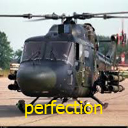 larrylynx
June 2, 2024 at 9:42 PM -
My 2 cents.
Go ahead and make your models but start with something smaller and simpler, to see how the FS4 workflow progresses. The 3d model can be the easy bit really as the TMD file needs to be mastered as well. It might look complicated for the advanced stuff but its much easier for a simpler aircraft and to get your feet wet. FS4 allows you to go crazy with detail and systems etc, as I am finding out with my C130, but it does take some serious amount of time for that amount of detail (modelling, textures and TMD). It will drive you crazy but its also very addictive

My comments are for PC as I do not have the mobile version and I know my stuff would never work on that platform.
Steve
-
It certainly does...........
-
Hey admin, any news on my requests. I can say 'pretty please' if it will help

-
If any one wonders where 600,000 polygons go, its here. Textures are just simple base ones for now.
-
Hi
Sometimes the amount of coding logic that goes into helicopters precludes them for mobile. As my systems logic is known just to myself it would take IPACS (Jetpack) some considerable time to make them mobile friendly and he doesn't have the time available as he is a very busy man. I do try to make them as accurate as I can which means some complex things are happening in the background. Actuated freewheels in my Lynx anr a good example. I doubt IPACS had any intention of that ever happening within the sim.
Poly count is also a big governing factor and I'm not shy on using polys. My C130 is already 630,000 polys and more to add.
I guess the short answer is, I build them for PC and VR. (and free)
With reference to the posted link. I did build a CH53E but could never manage anything more than a low hover, the complex nature of the engines/power/rotors etc finally beat me. Still have the WIP on my computer so who knows. Same problem which the Chinook or Legonook as it was to keep things simple. I say simple, just to get a Legonook into the sim requires all the engine/rotors/controls/fuel/electrics logic and once again, it beat me. The sim didn't seem to like two rotor systems. V22 may also suffer from this.
Steve
-
Matt, as a developer of great esteem you should know better than to ask for a sneak peek, but as its just you and me, here you go. and don't tell anyone.
-
I think Brave is a polite way of saying 'I Have lost my marbles'

-
Having driven a winch many many times (strange how people always forget about the winch driver and leave them down there for hours on end
 ) I do wonder about the size needed to get that glider in the air
 -
Hi Matt.
Only a fellow developer would spot such a thing. What made me chuckle was the colour. I got my RGB mixed up with RBG hence the lovely shade of Puce. It is indeed a Herc but the beast is certainly more complicated than I first thought and quite poly, switch and gauge heavy. 5 months so far but it is progressing and does fly. Minor task of autopilot and CDU to look at, textures and lots more cockpit modelling. Coding is already over 30000 and poly count has passed half a million. I would like to say it keeps me sane but that is subject to official confirmation, I am hoping this, and writing books, will ward off dementia as I am fast approaching that period in a person's life.
I also put some music in the apache but I doubt anyone ever noticed.
Steve
-
Being a developer can be pretty boring but occasionally it does make you smile.
-
HI and Welcome
In your Steam account (library) click on the FS4 Tab. Look in the righthand corner where it says, DLC, manage my DLC, click on that entry and it should take you to DLC tab, if they are all checked then they are installed.
Steve
-
Whilst I am being cheeky admin, can we have the Landing Lights on multiple entries, ie left and right. The 737 etc and the aircraft I am building have left and right switches and not just Landing Lights, thanks
Steve
-
Started 29 Dec 2023 and the last 3 months just working on the TMD file alone. Stops me getting bored and keeps the 67 year old brain active.