Table of Contents
Aircraft Repaints
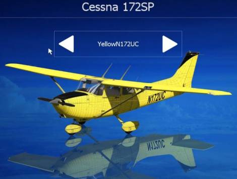
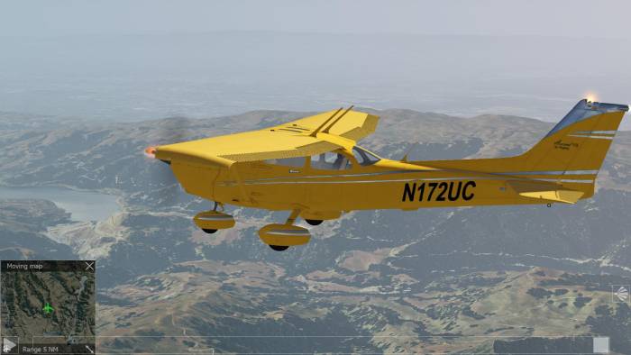
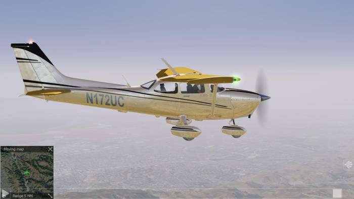
In this tutorial you will learn how to manually repaint an aircraft and insert your newly painted aircraft into the aircraft's preview. In this tutorial we will add a new repaint to the Cessna C172. Note - the designated name of this repaint is YellowN172UC.
Prerequisites
- Photoshop or Gimp- Needed if you want to use the PSD templates
- Aerofly FS 2 SDK package, see SDK introduction.
Setup
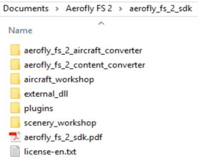
- Unzip the aerofly SDK package.This is the content of the directory.
- Locate and open the Aerofly_fs_2_aircraft_converter folder and run the executable located inside the folder.
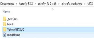
- Open the folder aircraft_workshop, go to and open the C172 folder, inside of the folder create a subfolder YellowN172UC.
- Copy the files from subfolder _textures to the YellowN172UC folder that you just created, add the file repaint.tmr
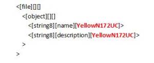
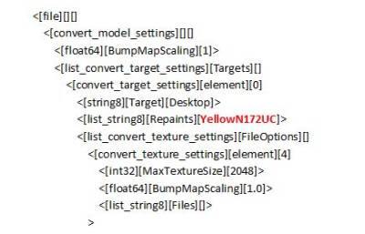
- Edit repaint.tmr using Wordpad or your favorite editing program and enter your new repaint name
- Next,edit model.tmc and enter your repaint name
- Now use Gimp or Photoshop to repaint the templates. See Repainting Tutorial for a detailed tutorial on this.
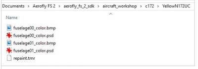
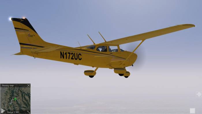
- Save 24-bit BMP. Note - The result should look like this.
File Conversion
Your files should all be ready at this point for the file conversion. Note - For the file conversion process to work properly, make sure that you have the latest SDK installed.
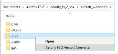
- Right Click on the c172 folder and select Aerofly FS 2 Aircraft Converter
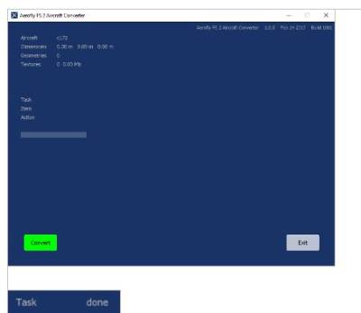
- Press the convert button the begin. Note - Wait until the conversion process is complete.
- As a result, you will see the converted files inside the Aerofly FS 2 folder.
- Test to see your new paint job.
Note - This tutorial can change to reflect changes to the SDK. A special thank you to “Karl-Heinz” for the writing of this tutorial.
Repainting Your Aircraft
This is a description of the PSD templates. You have to use Photoshop or Gimp to take advantage of the predefined layer structure. This tutorial will not explain how to use Photoshop or Gimp. Please refer to the related manuals. In this example we will use the files for the Cessna C172.
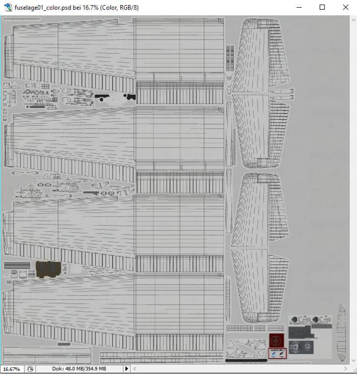
- Open the fuselage01_color.psd and fuselage0_color.psd.
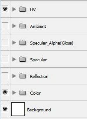
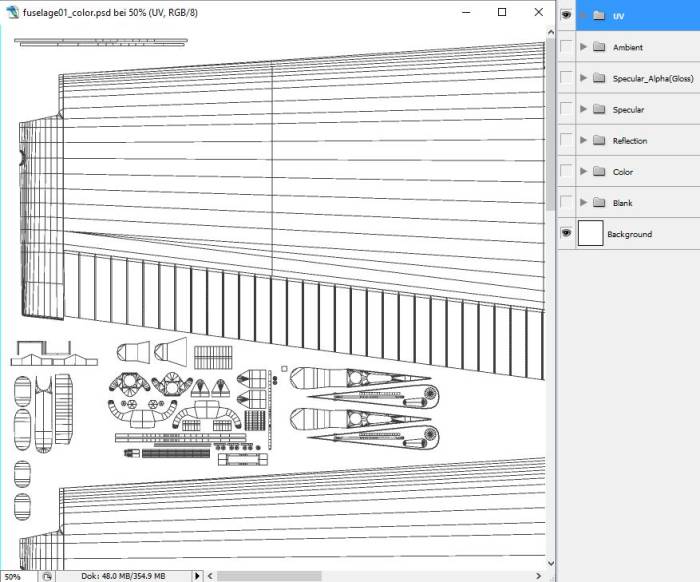
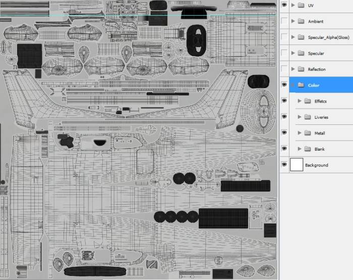
This is the structure of the layer groups that you will see in PS or Gimp.
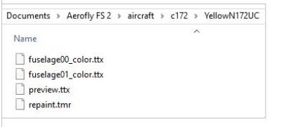
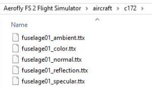
This is a directory listing of the graphics files that you will see in Aerofly FS 2 aircraft folders.
Note - As you can see, the PSD layer structure corresponds strongly with the files of the c172. This means, you can use the layer groups to output your repaint to the required BMP files.
UV layer group
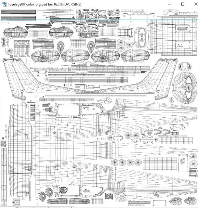
This group contains the display of the 3D mesh. This will give you orientation while repainting the aircraft. If left on when saving a BMP, the gridlines will appear on the aircraft. During repaint process the mesh can help to localize certain positions on the aircraft. Before we finally save a BMP, this group has to be switched off!
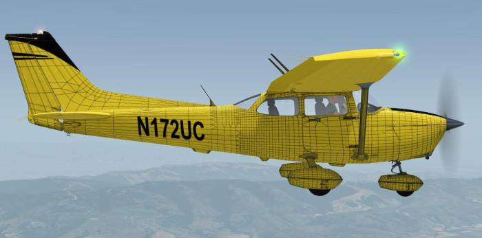
Here the fuselage00_color.psd has been saved with both layer groups on: Color + UV. The 3D mesh on the aircraft facilitates the identification of positions.
Detail of 3D mesh on UV layer
Color layer group
This is the main layer group for our repainting.
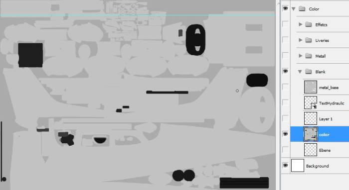
As you can see below, the Color layer group contains several subgroups like Effects, Liveries, Metal, Blank.
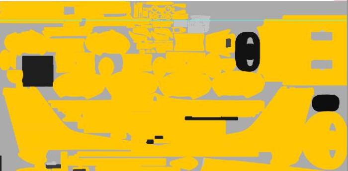
Next, switch off all layers except the single color layer. Now let’s change the basic color of our aircraft to yellow.
- Do not place lines, text and other objects onto this layer.
- Use separate layers for other objects. This allows easier adjustment of a line above the color drawing. You can move it, bend it, cut it without touching the base layer. Also you can copy and mirror the line layer to cover the other side of the fuselage or wing. The same is valid for text information. I even have separate text layers, which allows different fonts, positions, text sizes etc.
Liveries Group
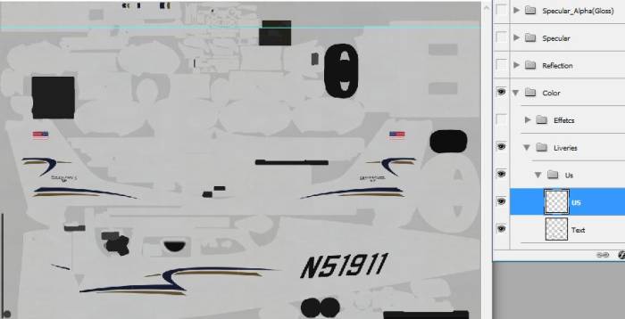
In the template you can see the design layers in the Liveries group.
Adding new layers with your designed content makes it easier.
If you finished repainting, switch on all necessary layers of the color layer group, switch off all other layer groups and save your work as _color.bmp, 24 bit. This will be used for conversion to the final _color.ttx file.
Ambient layer group
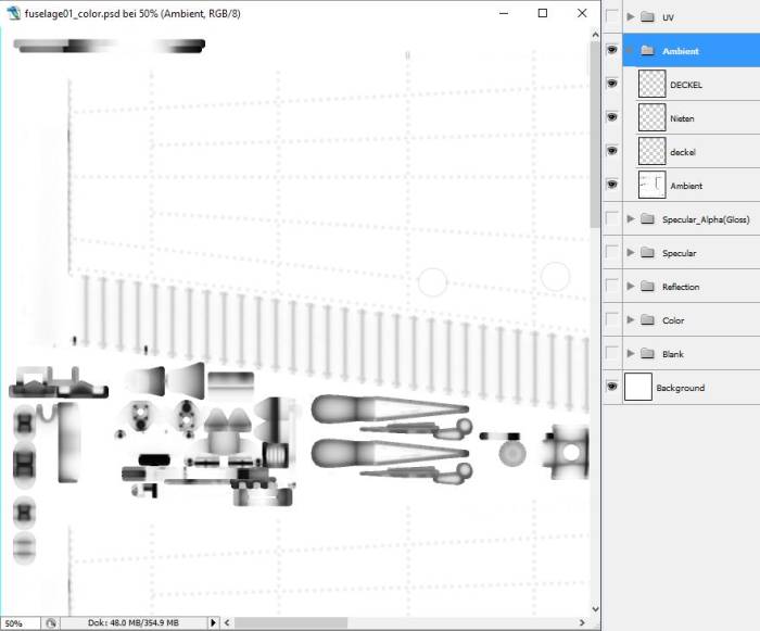
In computer graphics, ambient occlusion is a shading and rendering technique used to calculate how exposed each point in a scene is to ambient lighting. In aerofly FS 2 it is a 24 bit grey scale map.
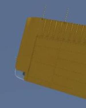
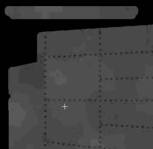
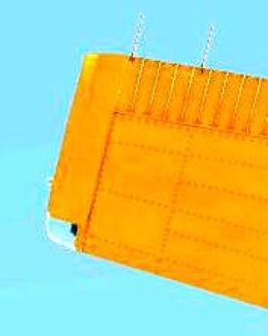
Note this groove line between the wing and the wing tip. In the color layer there is just yellow color. In the reflection layer we see the elevated rivets. But in the ambient layer the groove line is clearly visible.
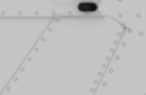
Note the rivets as small circles in this example (note: contrast has been modified for the tutorial).
- If you modified the ambient layer group, switch on all necessary layers, switch off all other layer groups and save your work as _ambient.bmp, 24 bit. This will be used for conversion to the final _ambient.ttx file.
Specular and Specular_Alpha layer group
24-bit color map with each color value representing the brightness for the Red, Green and Blue (RGB)
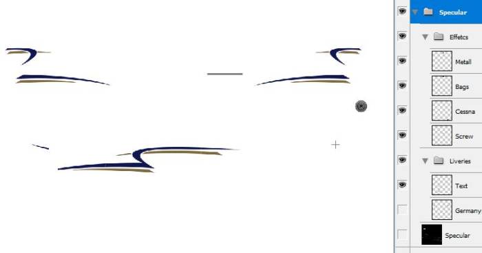
- As you can see, this group contains the signs of the original painting (note: for better demonstration, the black layer has been switched off)
- If we do not modify these layers, the shimmering will be visible on our aircraft.
If you modified the specular layer group, switch on all necessary layers, switch off all other layer groups and save your work as _specular.bmp, 24 bit. This will be used for conversion to the final _specular.ttx file.
Reflection layer group
This group controls the reflection strength of a surface. In aerofly FS 2 it is a grey scale layer group where black means no reflection and white means 100% reflection.
In this example I copied the aircraft lines onto the reflection layer and selected a bright grey
If you don't switch on the black layer the reflection layer will show white showing a perfect polished aluminum
Here is another detail of reflection layer group
The yellow is all plain-colored over the whole color layer. But in the reflection group the surface is not a uniform grey tone, it differs slightly in kind of patches. This creates a very realistic surface structure (note: contrast of screenshots has been modified to better display the patches).
- If you modified the reflection layer group, switch on all necessary layers, switch off all other layer groups and save your work as _reflection.bmp, 24 bit. This will be used for conversion to the final _reflection.ttx file.
As we have seen there exist several layer groups corresponding to different .TTX files of the aircraft. It is important to check and modify all of the related layer groups for our repaints. We output several different BMP files with fixed naming conventions. The structure is given by the templates provided by IPACS, the aerofly FS 2 developers. The result will be a high quality texture for our aircrafts.
