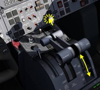
Table of Contents
**REDIRECTION NOTICE**
Learjet 45
Introduction To The Flightdeck
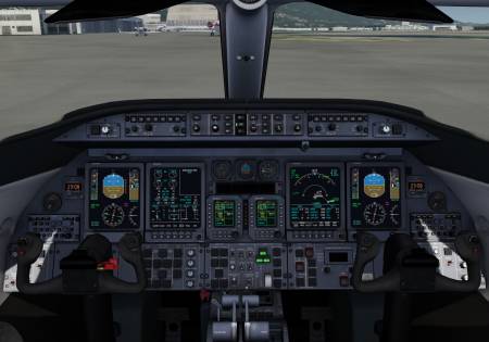
Welcome to the flight deck (also called “Cockpit”) of the Learjet 45. The flight deck can be divided into the front panel, pedestal and glareshield and does not feature an overhead panel.
On the front panel we find several displays which can be reconfigured if needed. From left to right these monitors show the left Primary Flight Display (PFD), the Engine Instrument and Crew Alerting System (EICAS), the two Radio Management Units (RMUs), the Multi Function Display (MFD) and the right PFD.
In the glareshield two display controllers for the onside PFDs and one Flight Guidance Controller (FGC) are positioned.
PFD
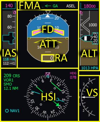
The Primary Flight Display (PFD) of the Learjet 45 is very similar to airliner PFDs. It features the typical layout with the attitude indicator (ATT) in the center with the flight director (FD), the indicated airspeed (IAS) on the left, altitude (ALT) on the right and a digital radar altitude (RA) at the bottom of the attitude. On the lower half of the display the Horizontal Situation Indicator (HSI) and Vertical Speed Indicator (VS) can be found.
FMA
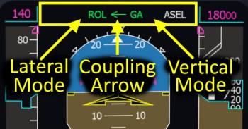
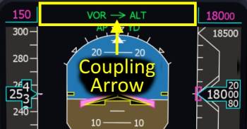
The Fight Mode Annunciator (FMA) is located in at the upper edge of the primary flight display (PFD). On the left side it indicates the lateral mode of the flight director (autopilot roll steering) and on the right it displays the vertical mode. In the middle of the FMA the coupling arrow can be found.
- Lateral Mode - Flight guidance function for roll
- Vertical Mode - Steering mode for pitch
- Coupling Arrow - Points towards the PFD that is relevant to the autopilot.
Coupling Arrow
If the arrow points away from the onside PFD it means that the navigation source on the other side is used. If we are looking at the left side PFD and the arrow points to the left that means our navigation source is used by the autopilot. If it would be pointing to the right it shows that the copilots PFD would be used instead.
- Click the XFR button on the Flight Guidance Controller (FGC) to select the left or right PFD as source for the flight guidance/autopilot.
PFD Bezel Controller
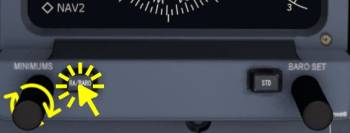
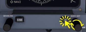
On the display frame of the Primary Flight Display (PFD) two pushbuttons two rotary knobs can be found. These are used to set minimums and pressure setting.
Minimums
In the Learjet 45 either a minimum Radar Altitude (RA) or minimum Barometric Altitude (BARO) can be set for the the approach. During the final approach a black and yellow “MIN” will flash on the PFD upon reaching the selected minimum radar or baro altitude.
- Click the RA/BARO pushbutton multiple times to switch between the modes RA, BARO or none. In the lower right corner of the attitude indicator the selected minimum will be displayed.
- Using the mouse wheel over the lower left knob increase or decrease the selected value.
Barometric Pressure Reference
The barometric reference for the altitmeter can be adjusted with the knob and pushbutton on the lower right of the PFD frame.
- Rotate the knob using your mouse wheel to increase or decrease the selected pressure value. The exact value is displayed below the altitude tape on the PFD.
- Click the “STD” button to insert the standard pressure value of 1013 hPa or 29.92 inHg. Pressing the button a second time doesn't change the setting back. Use the knob for this.
Display Controller
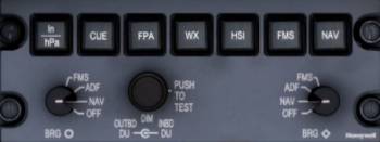
The Display Controller can be found in the glare shield of the Learjet 45. It controls mainly the Primary Flight Display (PFD). Click each button multiple times to experiment with its associated function.
- In/hPa - Changes the altitmeter unit on the PFD from Inches of mercury (inHg) to Hekto Pascals (hPa) and back.
- CUE - Toggles the flight director style from a single cue to a cross bar flight director
- FPA - Adds or removes the Flight Path Angle (FPA) from the attitude indicator.
- WX - Selects or deselects the drawind of the weather radar. (Weather radar currently not implemented, 2017-08-28)
- HSI - Selected between the 360° rose or 90° arc mode of the HSI. With the navigation source on FMS1 or FMS2 a 90° arc mode with a map for the flight plan is available as well.
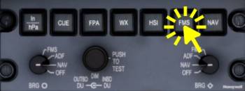
- FMS - On first click activates the FMS1 as navigation source. Following clicks alternate between FMS2 and FMS1.
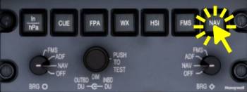
- NAV - On first click the NAV1 source (VOR1 or ILS1 depending on tuned frequency) is selected. Following clicks alternate between NAV2 (VOR2 or ILS2) and NAV1.
The two BRG knobs can be rotated with the mouse wheel and select the bearing needle sources. The left knob selects from FMS1, ADF1, NAV1 (VOR1) or OFF and the right one lets you chose between FMS2, ADF2, NAV2 (VOR2) or OFF. Depending on the source selection and their availability (signal strength or flight plan) the bearing needles on the HSI point towards the station or next waypoint in relation to the current heading.
Note - The bearing knobs as well as the HSI mode, dual/single cue flight director, weather radar or pressure unit don't have any affect on the autopilot. The navigation source selection (FMS and NAV button) does have an significant effect however.
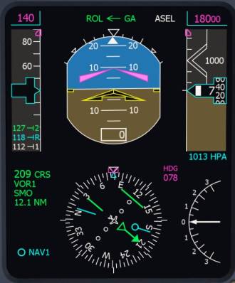
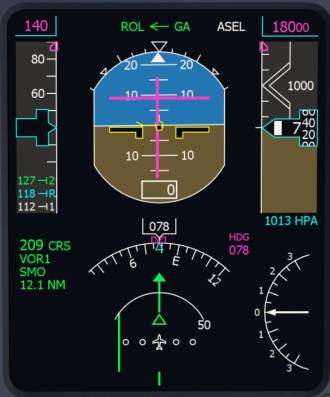
Here are two example screenshots to visualize the effects of these customization options:
- Single Cue Flight Director on the left and Dual Cue FD on the right
- Rose HSI mode on the left, ARC on the right
- Bearing 1 with NAV1 needle on the left and OFF on the right
- Flight Path Vector (Flight Path Angle FPA) visible on the right, parked in yellow on the horizon line
HSI Navigation Source Selection
In total the flight guidance (autopilot) can use one of four different navigation sources: Flight Management System (FMS) FMS1 or 2 or Navigation receiver NAV1 or NAV2. Depending on the frequency the receivers are tuned to the PFD will display “VOR1”/“ILS1” or “VOR2”/“ILS2”.
Here are two screenshots with the FMS1 as source on the left and VOR1 as source on the right screenshot. The currently selected source is always displayed in a legend left of the HSI. FMS sources are usually white and VOR/ILS sources are green unless the copilot and pilot PFD have the exact same source selected. When both sources are the same they are painted in yellow to warn pilots that they might accidentally affect the source of the other side (e.g. change the active course).
Selected PFD
The flight guidance uses the HSI on the PFD where the coupling arrow (see above) points to. To change the selection from left to right or vice versa:
- Click the “XFR” putton on the Flight Guidance Controller (FGC).
FMS Navigation Source
Both navigation sources, Flight Management System 1 and 2 (FMS1, FMS2) provide a lateral offset and a target track which is displayed on the Horizontal Situtation Indicator (HSI) when the FMS is the navigation source. The flight guidance uses these to steer the aircraft towards the route.
- A flight plan has to be set up in the navigation menu of the Aerofly FS simulator.
- Click the FMS push button on the Display Controller to select FMS1 or 2. Currently (2017-08-28) there is no difference between FMS1 or 2 implemented, later on the flight plans programmed in each of these devices may differ. Use the one which has the correct flight plan programmed.
- Click the “NAV” button on the Flight Guidance Controller (FGC) to arm lateral navigation from the Flight Management System (FMS).
- Once the route is intercepted the flight guidance will activate FMS mode and follow the flight plan.
VOR Navigation Source
The Learjet 45 is capable of flying towards the selected course along a VOR radial. The flight guidance uses the selected course, the needle deflection and distance (if available) to capture and maintain the VOR.
- Tune in the VOR frequency with the Radio Management Unit (RMU).
- Click the NAV pushbutton on the Display Controller once or twice to select the correct navigation receiver
- Rotate the Course knob on your side to change the desired inboard course.
- Click the “NAV” pushbutton on the Flight Guidance Controller (FGC) to arm VOR capture.
- Once the needle moves towards the center the VOR mode will capture and the flight guidance steers the aircraft along the radial towards the selected course.
MFD
The Multi-Function Display (MFD) of the Learjet 45 always displays the MAP/PLAN in the upper half of the display as well as one of the following pages in the lower half:
- SUMRY - Summary page of the electrics, hydraulics system and flight control trim values
- ELEC - Electric system
- HYD - Hydraulic system
- ECS - Environment Control System (ECS), air conditioning and pressurization
- FLT - Flight controls, position of trims and flap and spoilers
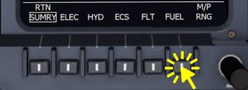
- FUEL - Fuel system, fuel levels
- TCAS - Small map of surrounding traffic as indicated by the Traffic Collision Avoidance System (TCAS)
Map/Plan Mode
The upper half of the display either renders a Map or a Plan view. The map is an arc section of the flight plan and other navigation aids and the plan mode is a north-up 360° compass rose display.
To toggle between the map and plan mode:
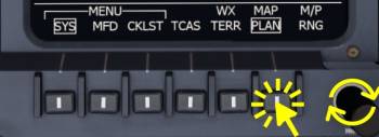
- Click the MAP/PLAN button in the main menu of the MFD
To adjust the range of the MAP/PLAN view
- Rotate the M/P RNG labeled knob of the MFD in the lower right corner by pointing at it with the mouse cursor and rotating the mouse wheel.
Note - The next screenshot shows the 360 PLAN mode on the left and the default arc MAP mode on the right.
Map Data
Optionally the navigation stations, airports and waypoints can be displayed additionally to the flight plan. To select these rendering options go to the main menu of the MFD and then click the MFD menu button. Now click the NAV/APT labeled bezel button as well as the DATA button.
TCAS
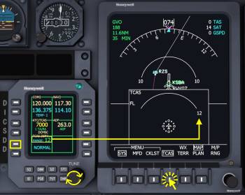
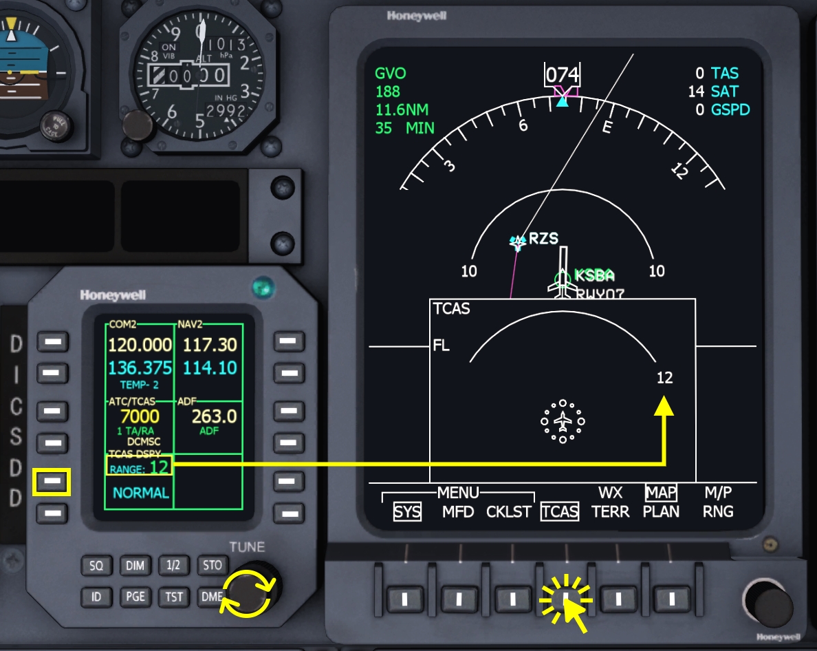
To display potential intruders on a map the MFD has a dedicated Traffic Collision Avoidance System (TCAS) map area with a separate zoom level than the Map/Plan in the upper half of the display.
To select the TCAS view
- Click any RTN labeled buttons to return to the main menu, if not already displayed (default position)
- Click the TCAS bezel button (third bezel button from the right)
- Click the same button again to hide the TCAS display later
To increase or decrease the range of the TCAS display
- Click the line select key next to “TCAS DSPY” Range on the Radio Management Unit (RMU)
- Scroll with your mouse cursor pointed at the small TUNE knob of the RMU
In a similar fashion you can change the TCAS tilt:
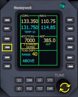
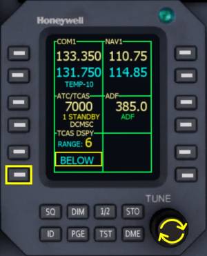
- Click the lower left line select key of the RMU, labeled “TCAS DSPY” ABOVE/NORMAL/BELOW
- Rotate your mouse wheel over the TUNE knob of the RMU to select the TCAS tilt.
System Pages
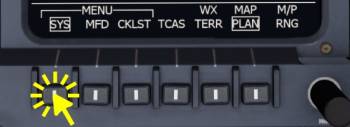
To select a system page exit out of any previous menu by clicking the bezel button labeled “RTN” (return) or deselect TCAS to get to the main menu.
From the main menu
- Click the SYS button. The system summary page or any other previously selected page will be displayed now
- Click any of the bezel buttons to select a system page
- After selecting a page, the “RTN” text will be visible above the page name, pressing the button again returns to the main menu.
V-Speeds
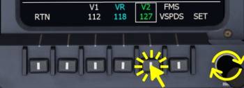
In the Learjet 45 the V-Speeds displayed on the PFDs are set from the MFD menu.
To enter the V-Speed menu in the MFD
- Go to the MFD main menu by following pressing the “RTN” labeled buttons or deselecting TCAS from the main menu
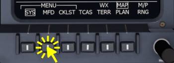
- Click the MFD labeled button
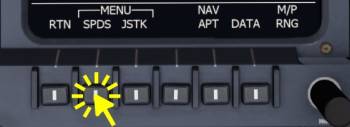
- Click the SPDS labeled bezel button
- Click the V-Speed that you want to edit
- Use your mouse wheel over the lower right knob of the MFD to increase or decrease the selected v-speed.
- Press the lower left “RTN” button twice to return to the main menu
RMU
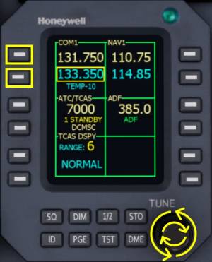
In the center of the front panel of the Learjet 45 we can find two Radio Management Units (RMUs) that allow manipulation of the communication and radio navigation receivers of the aircraft. In general the RMU is used in the following way: line select the standby frequency, use the adjustment knobs to step the standby frequency then swap the frequencies to activate the set standby frequency.
COM 1/2
The Learjet 45 has two radio communication (COM) transceiver (transmitter and receiver): COM1 and COM2. To change the frequency of the COM1 transceiver:
- Click the line select key next to the COM1 standby frequency if the device cursor isn't at the COM1 position anyway
- Move the mouse cursor over the adjustment fine and coarse knob and use your mouse wheel to turn them and adjust the standby frequency
- Click the upper line select key, next to the COM1 active frequency, to transfer the standby frequency into the active field
NAV 1/2
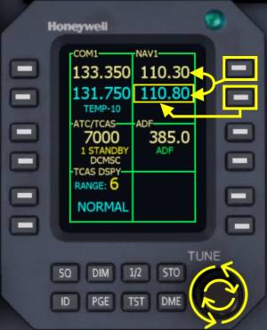
The RMUs in the Learjet 45 provide the necessary access to the navigation receivers to change the frequencies for VOR or ILS reception. The Learjet has no auto-tuning ability and the pilots have to set the desired frequency and course manually. Per default the left RMU displays NAV1 and the right RMU displays NAV2 but you could access either receiver from either device with the second page (PGE button).
- Click the lower line select key next to the navigation receiver 1 or 2 (NAV1, NAV2) frequencies. The display will highlight the standby frequency with a yellow box.
- Move the mouse cursor over the knobs in the lower right corner of the device
- Rotate the mouse wheel over the inner knob to change the decimals of the standby frequency (+/- 0.25 kHz)
- Use the outer knob to for a coarse +/- 1.0 Mhz step.
- Click the upper line select key to swap the active and standby frequency.
ADF 1/2
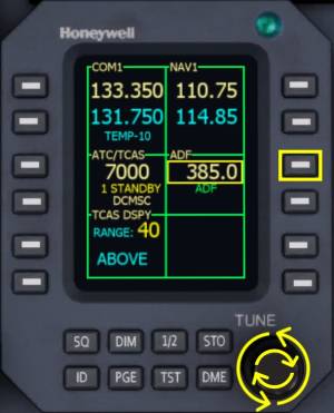
Depending on the Learjet version there may either one or two Automatic Direction Finder (ADF) receivers installed. The Learjet 45 for the Aerofly FS has only one ADF receiver. Both RMUs can change the ADF receiver frequency.
- Click the line select key next to the ADF frequency field.
- Mouse over the inner or outer knob and rotate your mouse wheel to adjust the active frequency.
Note - There is no standby frequency field available, only the active ADF frequency.
ATC/TCAS
Similarly to the ADF frequency adjustment the transponder squawk code can be set. But this isn't fully implemented yet (2017-08-29) so I'm abbreviating it here.
- Click the line select key next four digit squawk code
- Use the coarse and fine knob as shown above to change the squawk code. In the real world the increment speed is adjusted depending on how fast the knobs are turned, this is not yet implemented either.
The state of the ATC/TCAS system can be change from STANDBY to Traffic Advisory (TA) only (“Traffic Traffic!” or TA/RA (Traffic Advisory and Resolution Advisory): “Climb, Climb NOW!”.
- Click the lower line select key next to ATC/TCAS box.
- Scroll with your mouse wheel, with the mouse cursor over the fine adjustment knob to step through STANDBY, TA and TA/RA
Note - TA and RAs are not yet implemented (2017-08-29).
TCAS DSPY
The Traffic Collision Avoidance System (TCAS) Display area on the Multi Function Display (MFD) of the Learjet 45 (TCAS DSPY) can be adjusted to filter out traffic above or below the planned flight path or in the distance, out of close range.
A computational tilt “ABOVE” removes traffic that would be an issue in the descent and similarly the tilt “BELOW” only shows traffic that is a threat in the descent. In the “NORMAL” setting only traffic at similar altitude is shown.
The TCAS tilt (above, normal, below) can be changed as follows:
- Click the line select key next to the “ABOVE”,“NORMAL” or “BELOW” field in the lower left corner of the display.
- Mouse over the fine adjustment knob and use your scroll wheel to step up (towards above) or down (towards below)
The TCAS range as seen on the MFD TCAS view can be changed with the RMU as well. This allows us to zoom in when there is traffic nearby or to zoom out to get a better picture of the incoming traffic.
- Click the line select key next to the TCAS DSPY (TCAS Display) Range field.
- Use the fine adjustment knob to step through the available ranges (6, 12, 20 and 40 NM)
FGC
The Flight Guidance Controller (FGC) is the panel which is used to interact with the autopilot, or generally speaking the flight guidance. It dominates the glare shield and is quite accessible there for the pilots.
Summary Of The Functions
FD, AP, XFR, YD
- FD1 and FD2 - Flight Director clear buttons. If autopilot is off they remove the onside flight director from view. When autopilot is on the flight director button on the side where the couple arrow points to acts as a clear command to remove all active modes and return to basic pitch (PIT) and bank (ROL) hold. When the autopilot is off and no mode has been selected yet the buttons have no function.
- AP - Autopilot master, can be used to activate or disable the autopilot, button is illuminated when the autopilot is on
- YD - Master switch for the Yaw Damper, selected off before landing and set on after takeoff.
- XFR - Switches the PFD from left to right and vice versa.
CRS 1/2 Knobs
- Change the course of the onside PFD. Caution: When the navigation source on the PFD is illuminated in yellow a change of the course will affect both PFDs at the same time.
Lateral Modes (Left Side)
- The HDG knob is used to change the selected Heading. A digital readout of the currently selected heading can be found on both PFDs top right of the HSI (in magenta).
- The HDG pushbutton selects the lateral mode “HDG” to steer the aircraft towards to selected heading
- NAV - Activates lateral steering using the selected navigation source (FMS/VOR).
- APP - Similar to the NAV button but with higher precision used for FMS or ILS approaches.
- BNK - Reduces the bank limit of the autopilot to 14° for higher comfort.
Vertical Modes (Right Side)
- SPD button - Activates speed hold (IAS or MACH climb/descent) and pitches up to reduce speed, nose down to gain speed. Current airspeed or mach number is synchronized at the beginning.
- FLC button - Flight Level Change (FLC) (1 click) or Flight Level Change Highspeed (FLCH) (2 clicks) fixed speed profiles are used as a reference speed for the autopilot pitch command.
- VS button - Selects the Vertical Speed (VS) hold mode. Vertical speed is always synchronized when this mode is selected.
- VNV button - Arms the Vertical Navigation function which uses the vertical flight plan from the FMS. Only works with FMS as navigation source and only for the descent when the selected altitude is below the current altitude.
- ALT knob - Changes the selected altitude
- ALT button - Commands an instant level off at the current altitude. Target altitude is the altitude at the time the button is pressed.
SPD Knob
- Changes the selected airspeed in IAS vertical mode
- Changes the selected Mach number in MACH vertical mode
- Changes the selected vertical speed when in VS vertical mode
Flight Guidance Modes (Autopilot)
Lateral Modes
The following lateral modes are available in the Learjet 45: ROL, HDG, VOR, FMS, LOC and VAPP (not implemented yet). By pressing the same button twice the basic ROL mode is restored.
- ROL - Basic lateral mode to maintain bank angle/roll attitude. Below roughly 6 degrees the wings are leveled and current heading is maintained, above that angle the current bank is maintained.
- HDG - Turns towards the selected heading value. When the HDG knob is rotated in one direction the aircraft will turn that way even if the turn in the other direction may be quicker.
- VOR - Flies a VOR radial and uses the navigation receiver lateral offset
- FMS - Reduces the lateral offset to the flight plan and flies towards the FMS target track
- LOC - Captures and maintains an ILS localizer.
Vertical Modes
In the Learjet 45 we can chose between these vertical modes: PIT, IAS/MACH, VS, ALT, FLC/FLCH, VNAV, GA and ASEL. By deselecting any vertical mode, e.g. by pressing the associated button again, the basic PIT mode is restored.
- PIT - Maintains the current pitch attitude. In the real world Touch Control Steering (TCS) could be used to change the attitude with the yoke. This is currently (2017-08-28) not implemented yet.
- IAS/MACH - Pitches up or down to accelerate or descelerate towards the selected airspeed or Mach number value.
- VS - Maintains the selected Vertical Speed value
- ALT - Maintains the target altitude which equals the altitude at the time the mode was selected. This mode is not affected by the selected altitude!
- ASEL - Captures and maintains the selected pressure altitude.
- FLC and FLCH - Uses a static speed profile for climb or descent. In contrast to the IAS/MACH hold this mode will not descent when the selected altitude is higher or climb if the selected altitude is lower. It only flies towards the selected altitude, never away. FLC is normal Flight Level Change and FLCH is Flight Level Change High Speed in the Learjet.
- VNV - Vertical Navigation, can be used for the geometric FMS descent profile.
- GA - Fixed pitch up reference, cannot really be used as a guidance
Flight Management System (FMS)
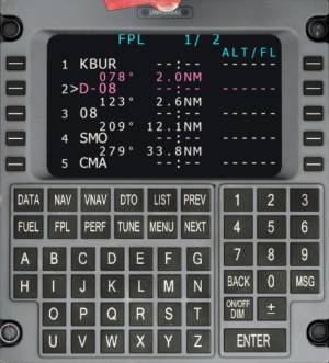
The Learjet 45 uses the Universal FMS which is also used in the Q400 and in the specific 737-500 simulated in Aerofly FS. The FMS is described in detail on the Universal UNS-1 wiki page.
Learjet 45 Flight Tutorial
Flight Plan
The flight for today is going to take us from Bob Hope, just North of Los Angeles, West towards Santa Barbara Muni. We're using the Learjet 45, pick any livery you like.
Create the flight plan as follows:
- Select Bob Hope (KBUR) as your starting location, Runway 8
- Select Santa Barbara Muni (KSBA) as your destination airport, ILS Runway 07
- Add the Santa Monica VOR: “SMO”
- Add the Camarillo VOR: “CMA”
- Add the Gaviota VOR: “GVO”
KBUR RWY08 SMO CMA GVO RWY07 KSBA
Briefing
This route is going to take us South-West first, to see the Hollywood Sign and the downtown city of L.A., we'll describe how to level off, fly manual heading and then resume the route but you can skip all this if you like. During the flight we're going to show how to intercept a VOR, you can skip this as well if you like. The parts that can be left out will be marked as optional. Weather or not you fly this little sight seeing tour is up to you, you could of course also repeat the flight and do it the second time if you like.
Towards the end of the flight we're actually not going to flying over the Gaviota VOR (GVO) because it bring us close to the mountains North of Santa Barbara and make the route quite a bit longer. I'm using GVO more as a fix to flip the approach to the North side of the airport which is more scenic and makes it a lot easier to spot the airport, because we'll fly almost over top it. We're then swing around manually and intercept the ILS at Santa Barbara in heading mode. Because we're not going the full length of the route to GVO the total distance of this flight will be less than the original 117 NM (216.7 km) and it should take us 30 to 45 minutes, depending weather you like to do the sight seeing at the beginning or just blast off Bob Hope and head up to the cruise altitude.
Cruise altitude for this flight is going to be FL 180, we should be able to reach that easily even with the optional sight seeing tour at the beginning, we're very light with a lot of thrust coming from the powerful engines.
Conditions
You can set the conditions as you like, we're going to use runways pointing to the East so wind coming from the East would be best.
Suggested conditions are
Time Of Day: 2300Z (3pm local)
Clouds And Visibilty
- visibility maximum
- cumulus cloud density: 50%
- cumulus cloud height: 50%
Wind
- 140° (SE)
- Strength: one slider width
- Turbulence and thermals as desired
Takeoff Data
For those who are interested here are a couple of infos for the current setup of the aircraft:
- Takeoff mass 7102kg, 15657 lb (fix),
- Takeoff trim will be 5.9 units
- Takeoff flap setting is 8°
Controls
Prior to the flight we recommend setting up a few key commands that we need during this tutorial flight.
Please go to the controller setup for the “autopilot” and
- assign a key for the autopilot “Disengage” command (takeover button) and
- the “Take off / go around mode” (TOGA button on the throttle levers).
In the “primary” control settings
- Assign a key command to the “Parking brake”.
Preparation
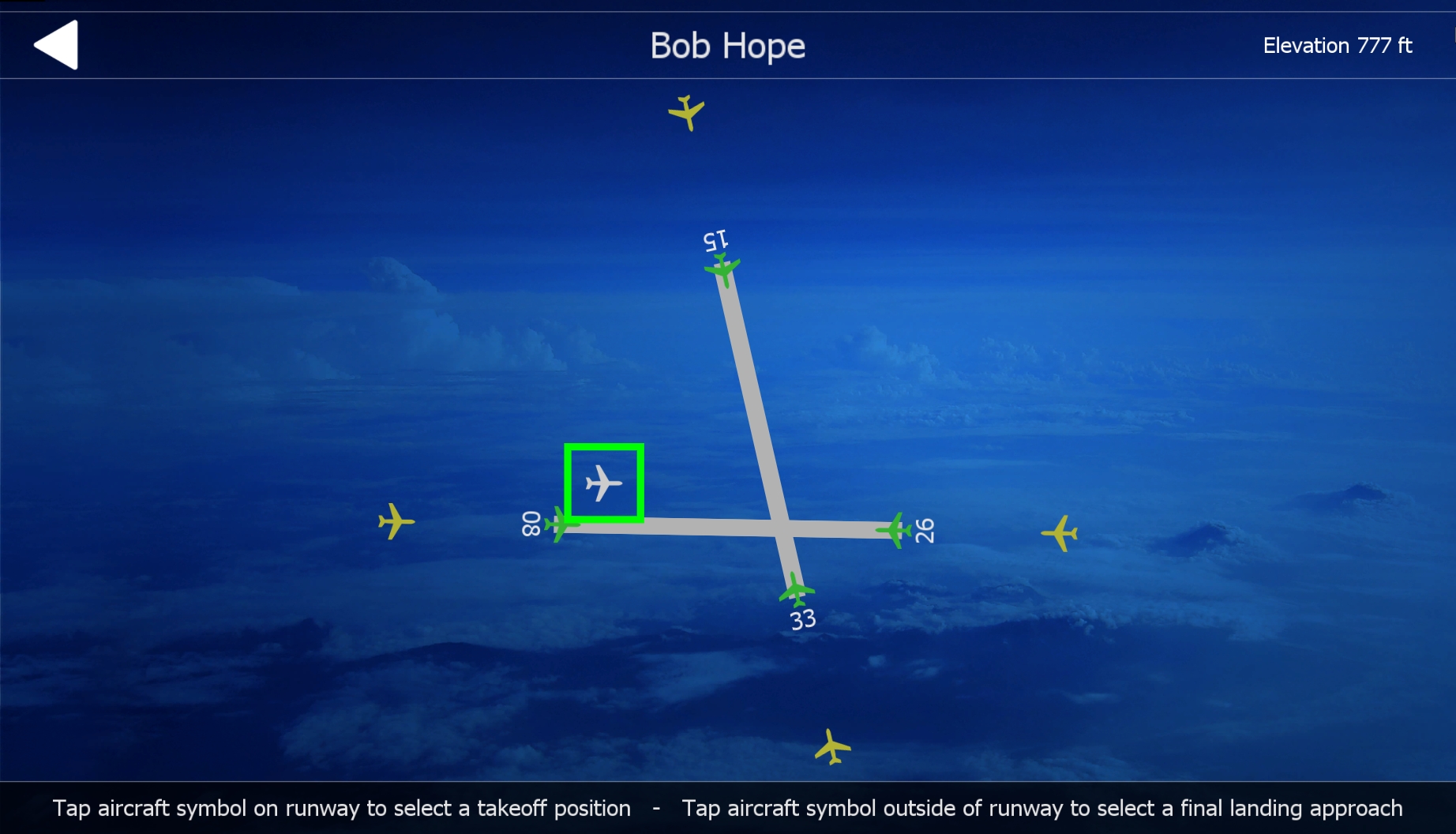
Now that everything is set up in the sim and for the route you can go to the location dialog, click on the Bob Hope airport and then select the white aircraft symbol to start the flight at the ramp. You can now start the simulation.
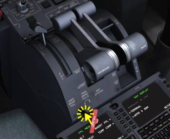
Set Parking Brake
When the aircraft has loaded and you find yourself in the cockpit please set the parking brakes right away so that we have time to prepare and perform a few actions before we start to taxi.
- Press the assigned key command for the parking brake
or
- Click the parking brake handle
or
- Hold down the left mouse button to grab the parking brake and move the mouse to drag the lever forward.
Setting V-Speeds
Let us quickly review the meaning of the three V-speeds: V1, VR and V2
V1 is the takeoff decision speed, also called “V go”. When a critical malfunction occurs like the failure of an engine we can abort the takeoff roll when we are slower than V1. When we are already faster then V1 either the runway is not long enough to stop from that point with that high speed or the maximum brake energy would be exceeded which may also result in an runway overrun. Above V1 we are committed to the flight, we have to continue the takeoff.
VR is the rotation speed at which the yoke is pulled aft to lift the nose off the ground.
V2 is the climb speed for the initial segment after lift off up to flap retraction. This speed is flown when one engine failed during the takeoff and we decided to continue into the air, above V1. Typically the speed actually flown in the first segment is V2 + 10 kts or faster.
With our current takeoff mass of roughly 7100 kg or 16,000 lb the v-speeds are:
- V1 = 105kt
- VR = 107kt
- V2 = 116kt
To edit the speeds we're going into the MFD menu as already shown in the cockpit introduction.
- Go to the MFD main menu by following pressing the “RTN” labeled buttons or deselecting TCAS from the main menu
- Click the MFD labeled button
- Click the SPDS labeled bezel button
- Click the V-Speed that you want to edit
- Use your mouse wheel over the lower right knob of the MFD to increase or decrease the selected v-speed.
- Press the lower left “RTN” button twice to return to the main menu
Selecting Runway Heading
For our own guidance we're going to put the heading bug to the runway direction, so that we have something to aim at after lift off to fly a straight takeoff.
On the Flight Guidance Controller (FGC)
- Move your mouse cursor over the heading knob and use your mouse wheel to rotate the heading knob to select a heading of 078, this should only take one tick to the right because we are already pointed almost parallel to the runway.
- Verify the “YD” button in the center of the FGC is off.
Note - Do not press any other buttons on the FGC at this time, there should be no button illuminated yet, except the XFR arrow. If there is any button illuminated: Click the left “FD1” and the right “FD2” buttons to set the flight director to off and clear all flight guidance modes.
Set Navigation Source to FMS
We're going to set the navigation source to FMS which will allow the autopilot to follow our flight plan and we also get the lateral offset to our flight plan on our PFD. In the air we are going to engage the flight guidance “NAV” mode which uses the selected navigation source to steer the aircraft. With our selected navigation source being “FMS” the NAV mode will give us a lateral navigation from the FMS (LNAV in other aircraft) which we need to fly along the route.
- Click the “FMS” pushbutton on the display controller left of the autopilot panel (FGC) to select the FMS1 as navigation source on our PFD.
Note - FMS1 should be indicated on the primary flight display, in the legend left of the HSI rose. If FMS2 is now showing that is fine, to set it to FMS1 just press the “FMS” button again.
After the selection of the FMS1 navigation source the PFD should look similar to the screenshot below. Notice the “FMS1” text on the left and the white deviation indicator and arrows on the Horizontal Situation Indicator (HSI). The white solid arrow of the HSI now points into the direction the flight plan would take us and the white bar over the aircraft displays the lateral deviation from the flight plan. At the moment it indicates that we are parallel to the flight plan but need to correct to the right a bit, which seems legit, since the runway 08 is the first segment of the flight plan and it is parallel and right of us.
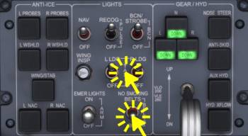
Lights
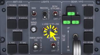
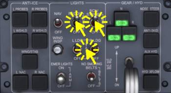
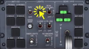
- Mouse over the BCN/STROBE switch and use your mouse wheel to set the switch to the intermediate BCN (beacon light only) position.
- Mouse over the RECOGnition light switch and scroll with the mouse wheel to set it OFF.*
- Also set off the left and right landing lights (L LDG, R LDG) to the OFF position in the same way.*
- Set the NAV lights to on.*
Note - The items labeled with (*) should already be completed by default, comfirm the switches are in the right position.
Before Taxi
Before we get rolling we're going to check the flight controls, move your control inputs to make sure they are working as intended.
Check Spoiler Extension
Also extend the spoilers and check if they extend symmetrically.
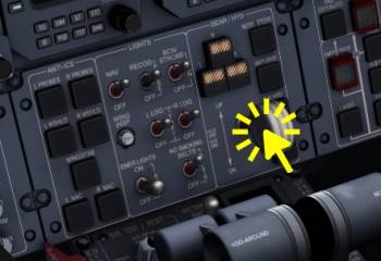
- Move your mouse cursor over the base of the spoiler lever or over the slot in the throttle quadrant where the spoiler lever shaft cuts through and rotate the mouse wheel over that area to extend the spoilers
or
- Point the mouse cursor at the spoiler lever tip, hold down the left mouse button and drag the lever aft.
The spoilers extension is visible on the Engine Indication and Crew Alerting System display (EICAS) in the Crew Alerting System (CAS) as text info “SPOILERS EXT” as well as in the spoiler position indicator.
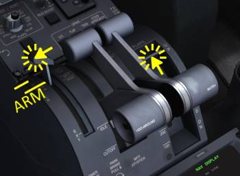
Arm Spoilers
- Move the spoiler lever all the way forward and just a tiny bit aft, to about 5% of the lever position where the “ARM” position is labeled.
This will arm the automatic spoiler extension in case of a rejected takeoff. The Crew Alerting System (CAS) will show “AUTOSPLR ARMED” in white.
Set Takeoff Flaps
- Either hold down the left mouse button and move the mouse to drag the flap lever or use your scroll wheel to set the flaps to the first setting, to 8°
Taxi Lights On
- On the LIGHTS panel, mouse over the the three state landing/taxi switch (“L LDG” and “TAXI” written next to it) and rotate your mouse wheel to set the switch to the middle “TAXI” position.
Release Parking Brake
We're ready to taxi and can now release the parking brake to get going.
To start taxiing, release the parking brake
- Press the assigned key command
or
- Click the parking brake handle
or
- Point at the parking brake handle and hold down the left mouse button and move the mouse to drag it.
Before Taxi Checklist
| Before Taxi Checklist | |||||
|---|---|---|---|---|---|
| No. | Location | Panel Name | Action | Remarks | |
| 1 | Controls | Flight Control | Free and correct | CHECKED | Test your assigned controls |
| 2 | Quadrant | Spoiler Lever | Autospoilers | ARMED | |
| 3 | Lower Front Panel | LIGHTS | NO SMOKING BELTS | ON | |
| 4 | Lower Front Panel | LIGHTS | TAXI LIGHTS | ON | |
| 5 | Lower Front Panel | GEAR/HYD | NOSE STEER | ON | Should already be on, button pressed in |
Taxi
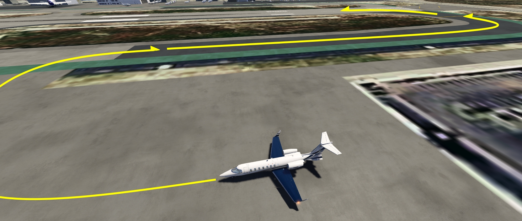
We're going to taxi out to Runway 8 which is already parallel to our parking position, off to our right. Turn right onto the taxiway and follow it onto the runway 8.
Preparing The Autopilot
- Press your “Takeoff / Goaround Button” which we assigned earlier in the control setup. The flight guidance will select the “ROL” lateral mode and the “GA” vertical mode for us, which can be seen on the flight mode annunciator (FMA).
Note - If you don't have the go-around button assigned you can also press the “HDG” pushbutton on the Flight Guidance Controller (FGC) to select the heading mode. The go around (GA) vertical guidance mode will automatically be selected as well. A second click on that “HDG” button will select the basic “ROL” mode and you should get the same result.
Selected Altitude
We're going to dial in the cruise altitude of 18,000 ft as our select altitude so that we can climb unrestricted. If you plan to do the little sight seeing tour select 2000 ft for now.
- Move your mouse cursor over the ASEL knob on the Flight Guidance Controller (FGC) and turn it with your mouse wheel until the Primary Flight Display (PFD) shows your desired altitude in the top right corner.
Brake And Reverser Test
- Tap the brakes gently to test if they are working
- Use your assigned thrust reverse to check if the reversers deploy and then store them right away.
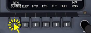
Select FLT And SUMRY Pages
To select a system page exit out of any previous menu by clicking the bezel button labeled “RTN” (return) or deselect TCAS to get to the main menu.
Please select either the FLT or SUMRY page on the EICAS and the other page on the MFD.
- Click any buttons on the bezel controller of the MFD that are labeled “RTN”.
- Once you are in the main menu of the MFD click the SYS button.
- Click the SUMRY button to select the system summary page.
- Click it again to return back to the main menu of the MFD.
Takeoff Trim
| Takeoff Pitch Trim | |||||||
|---|---|---|---|---|---|---|---|
| CG %MAC | 1 - 10 | 12 | 14 | 16 | 18 | 20 | >22 |
| Trim Setting | 8.7 | 8.1 | 7.6 | 6.4 | 6.4 | 5.9 | 5.3 |
Our center of gravity is about 20% MAC, that means we're going to use about 5.9 units of pitch trim. This should already be set and no action is required.
To manually adjust the pitch trim setting we can either
- use the assigned pitch trim control on our input device
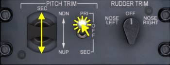
or with the control in the pedestal. But to use the control in the pedestal we first have to set the pitch trim switch to the SEC (secondary) position
- mouse over the PITCH TRIM PRI/OFF/SEC switch and rotate the mouse wheel to set the switch to the aft “SEC” position
- mouse over the black PITCH TRIM SEC rocker on the left and rotate the mouse wheel to set the correct trim
Note - This panel is located in the pedestal, near the pilot seat and aft of the FMS devices.
| Taxi Checklist | |||||
|---|---|---|---|---|---|
| No. | Location | Panel Name | Action | Remarks | |
| 1 | Controls | - | Brakes | TESTED | |
| 2 | Controls | - | Reverse | TESTED and STOWED | |
| 3 | Front Panel | PFD | V-SPEEDS | REVIEWED | |
| 4 | Front Panel | EICAS | TRIM | SET 3x | Pitch 5.9 units, Rudder and Aileron 0.0 |
| 5 | Front Panel | EICAS | FLAPS | INDICATION CHECKED | Flap display should display takeoff flap setting, 8° |
| 6 | Lower Front Panel | PAX OXYGEN | HI FLOW | OFF | Not modeled |
| 7 | Lower Front Panel | PAX OXYGEN | L/R BLEED | AS REQUIRED | Not modeled |
Runway Lineup
We're now cleared for takeoff and are rolling onto the runway and will do our spool up shortly. Before we takeoff there are a few items remaining that we can only do now.
ATC/TCAS
On the RMU
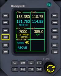
- Click the 4th line select key on the left.
- Scroll with your mouse cursor over the tune fine knob to step the mode from STANDBY, TA to TA/RA.
In a similar fashion you could edit the TCAS tilt but it should already be set to “ABOVE” so no action required here.
Note - The Traffic Collision Avoidance System is currently (2017-09-16) not implemented yet. So you can change around it's setting like you would in the real world but there aren't any aircraft yet that will trigger any warnings.
Lights On
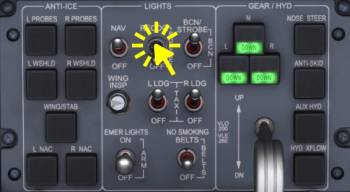
We are rolling onto an active runway and will therefor turn on our strobe light and also set the landing lights to on since we already have the takeoff clearance. Some Learjets also have recognition lights, we're going to set them on as well.
- Mouse over the BCN/STROBE switch and set it to the upper BCN/STROBE position with your mouse wheel
- Scroll over the REGOC switch to set the recognition lights to on (RECOG position)
- Set the left and right landing lights to on by scrolling over either the L LDG or R LDG light switch.
Note - The recognition lights affect the same light bulbs as the landing lights so you won't see any difference when you turn them together with the landing.
| Before Takeoff Checklist | |||||
|---|---|---|---|---|---|
| No. | Location | Panel Name | Action | Remarks | |
| 1 | Front Panel | RMU | ATC/TCAS MODE | TA/RA | |
| 2 | Front Panel | RMU | ATC/TCAS TILT | ABOVE | |
| 3 | Lower Front Panel | LIGHTS | L+R LANDING LT | ON | |
| 4 | Lower Front Panel | LIGHTS | BCN/STROBE | STROBE | |
| 5 | Front Panel | EICAS | PAGE | FLT or SUMRY | |
| 6 | Front Panel | MFD | PAGE | SUMRY or FLT | Different from EICAS |
Takeoff
Normal Takeoff Procedure
Hold the brakes. Advance your throttle control input forward until you see an N1 indication of 85 to 86% on the EICAS (first round two dials from the top). We call that takeoff thrust set, release your brakes.
The aircraft will accelerate quickly, maintain the center line of the runway with rudder and gently pull back when the speed exceeds VR of 107 kts. Rotate with about 3 to 5 degrees per second.
Positive Rate Gear Up
When airborne retract the landing gear.
- Click the landing gear lever to retract the gear.
Stabilize Pitch And Speed
Maintain a speed of about V2 + 10 kts, or roughly where the selected airspeed bug is placed, 140 kts. Ignore the flight director pitch guidance, it only indicates a fix pitch angle in the GA mode and is not meant as guidance.
Engage Autopilot
When above 500ft, with stabilized pitch attitude and stable speed, set the autopilot to on. Engage NAV mode now.
- Click the Autopilot Master (AP) button to engage the autopilot. Let go of your controls.
- Click the NAV button, the autopilot will then start tracking the flight plan, because we selected FMS1 as navigation source earlier.
- At 1000 ft click the FLC button on the Flight Guidance Controller (FGC) to select Flight Level Change (FLC) as new vertical mode
Note - When you chose the sight seeing tour and selected 2000 ft the autopilot will level off shortly, no need or time to set FLC. Reduce thrust to keep around 180 kts.
Maximum Continuous Thrust (MCT)
Set maximum continuous thrust (MCT) of around 83.2%.
Sight Seeing Tour (Optional)
As denoted earlier this part is purely optional and you can skip all the way to the “Climb” section of this tutorial. If you do want to do this maintain a speed of 180 kts for this right hand turn to work as intended with the autopilot or just fly manually.
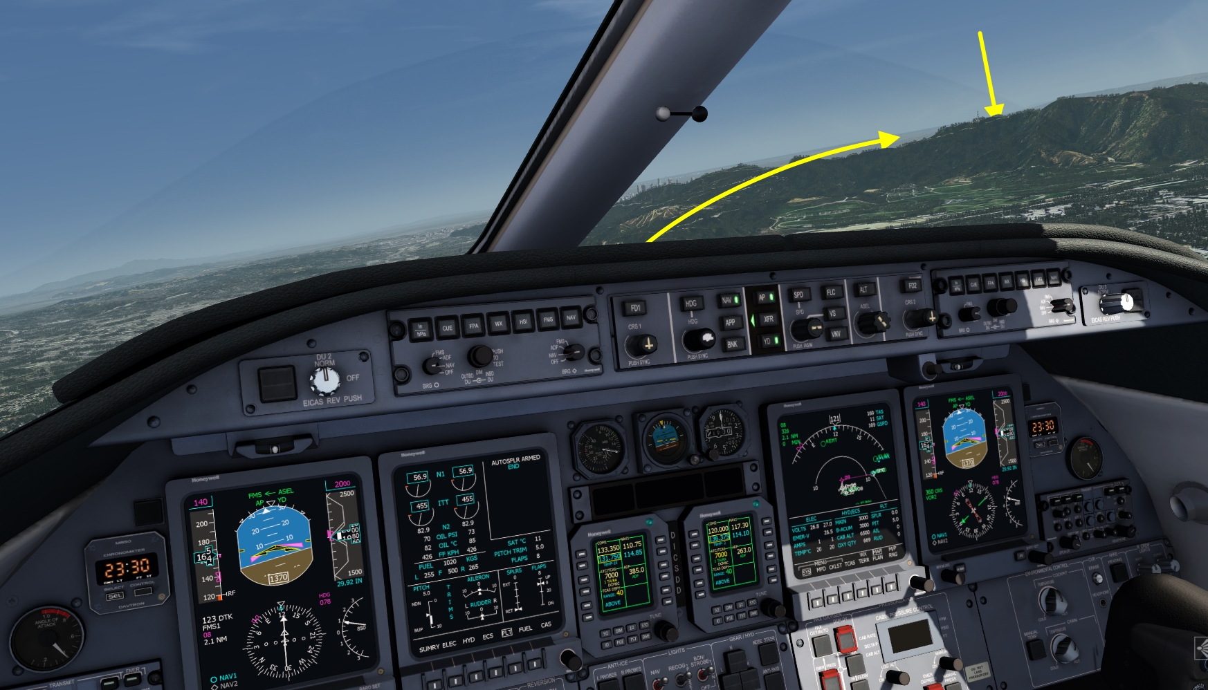
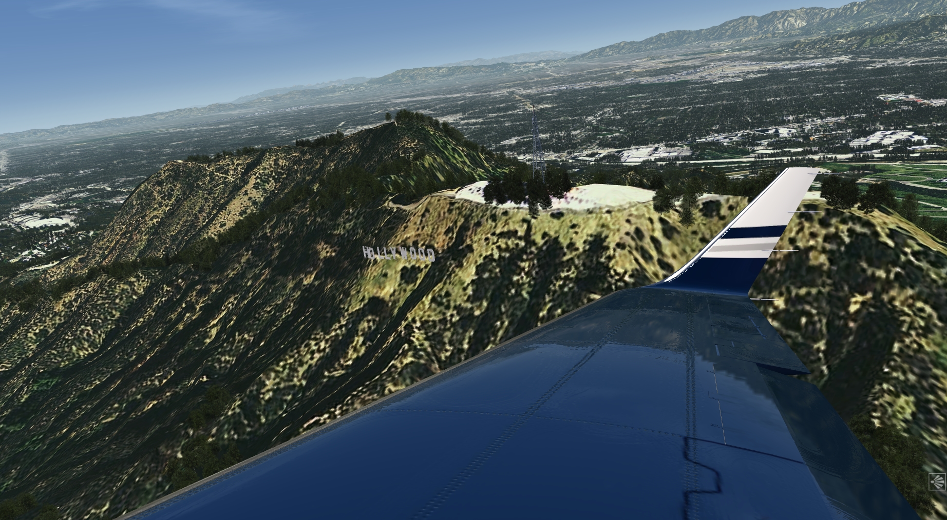
Plan is to swing around the hills off to our right. On the back side, facing L.A. there is the Hollywood Sign tourist attraction which our passengers want to see. There is also a little tower up on that hill which you should be able to see after the first right turn of the flight plan.
We're going to use heading select to steer around that mountain and we're only using half bank angle so that we can see the sign from the cockpit as well, even from our left seat if everything goes as planned. :) You can of course fly this part manually if you like, fly around the hill a couple of times.
This isn't totally realistic, you probably can't fly that close to the sign in real life, but hey, we're having fun and pretend to have rich people in the back who will pay for all fines, right?
Level Off
Because we set the selected altitude to only 2000 ft earlier the autopilot has already leveled off now. Another way to level off any time a.s.a.p. would be to press the “ALT” button on the FGC. The altitude at the time of the button press is stored as target altitude and the autopilot is going to maintain that altitude.
Reduced Bank Limit
As soon as the first right turn to heading 123 is completed by the autopilot select the reduced bank angle limit for the autopilot to make the upcoming turn a bit wider.
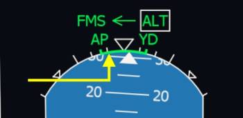
- Click the BNK button on the FGC. The PFD will now render a green arc at the top that indicates the bank limit of the flight guidance commands.
Fly Selected Heading
Now select heading 120° and fly a speed of 180 kts.
- Click the HDG knob first to synchronize the selected heading to the currently flown heading
- Rotate the HDG knob with the mouse wheel to 120°
- Click the HDG push button above the HDG knob to enter HDG select mode.
FMS Leg Switch, Heading 210
Watch the HSI on your PFD. When it flips right to the next waypoint and no longer points towards 123° wait 10 seconds, then rotate the selected heading right to 210°, still with reduced bank limit.
When you are confident you can turn further right at your discretion.
The Hollywood Sign
It should look something like this, when you are close to the sign.
Resume Flight Plan
Look at the PFD and depending on the position of the deviation bar adjust the selected heading left or right to reintercept the leg. Click the NAV button on the FGC as shown earlier. The autopilot will pick up the flight plan in FMS mode shortly.
Increase the selected altitude to FL 180 and press the FLC button as shown above. Advance the thrust to MCT to start climbing.
Climb
Retract Flaps, Disarm Spoilers
When we accelerated above V2 + 25 kts (141 kts today) we can select flaps up. And while we're at it, disarm spoilers.
- Scroll over the flap lever to set the flaps to up or
- Press you assigned key command or button to retract the flaps.
- Click the spoiler lever to disarm the auto spoilers or
- Press your assigned key command or button to retract the spoilers
Yaw Damper On
If you are not flying with autopilot you should turn on the yaw damper now for improved passenger comfort and better turn coordination.
- Click the YD button on the FGC
| Climb Checklist | |||||
|---|---|---|---|---|---|
| No. | Location | Panel Name | Action | Remarks | |
| 1 | Lower Front Panel | GEAR | GEAR POSITION | RETRACTED | |
| 2 | Front Panel | EICAS | FLAP POSITION | RETRACTED | |
| 3 | Front Panel | EICAS/SPOILERS | AUTO SPOILERS | RETRACTED | |
| 4 | Glareshield | FGC | YAW DAMPER | ON | |
10k And 18k Checks
10,000ft
At ten thousand feet altitude we can switch off the landing lights and release our passengers.
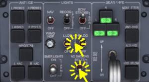
- Use your mouse wheel over the L LDG or R LDG light switches and turn them to OFF
- Scroll your mouse wheel over the NO SMOKING/BELTS switch to set the seat belts to the OFF position.
18,000ft, Standard Pressure
Reaching 18,000ft (transition altitude in the U.S.) we are going to set all three altimeters to standard pressure.
- Click the STD push button to insert the ISA standard pressure of 29.92 or 1013 hPa for the altimeter on the PFD, repeat for the right side
- Rotate your mouse wheel over the standby altimeter adjustment wheel to set 1013 or 2992, which should already be set.
Note - The pressure indication won't switch to a text “STD”, it just sets the pressure value to the standard pressure. To switch back to local pressure just turn the BARO SET knob right next to the STD push button on the PFD bezel selector.
Recognition Light Off
After reaching the transition altitude.
- Click the RECOGnition light switch
| Climb Checklist Continued | |||||
|---|---|---|---|---|---|
| No. | Location | Panel Name | Action | Remarks | |
| 1 | Lower Front Panel | LIGHTS | LDG/TAXI | OFF | Above 10k |
| 2 | Lower Front Panel | LIGHTS | BELTS | AS REQUIRED | Above 10k |
| 3 | Front Panel | PFDs, Standby ALT | ALTIMETER | STD 3x | Above 18k |
| 4 | Lower Front Panel | LIGHTS | RECOGNITION LIGHTS | OFF | Above 18k |
Cruise
Remember that this aircraft does not have an auto throttle system and we have to manage speed ourselves. Reduce the thrust to maintain a speed of about 280 knots, we used about 72% of N1 in our testing.
VOR Interception (Optional)
This is another optional part where we're going to intercept a VOR radial with the autopilot of the Learjet 45. Skip this section as desired.
The plan for this section is to get a better understanding of the navigation source selection and the coupling arrows and XFR switch. We're going to interact with the RMUs, use the copilot PFD to intercept the signal from nav source 2 and then resume the flight over Camarillo in FMS mode, before we need to start the descent.
We are at cruise altitude with a heading of about 278° or still during the climb, just after Santa Monica VOR (SMO) and well before the Camarillo VOR (CMA) station. We're going to intercept the 255° radial towards Ventura VOR (VTU) and then turn back onto the flight plan, for this we will prepare everything on the right PFD and then just switch the navigation source from left to right PFD with the XFR switch.
Navigation Source Selection
NAV2 should already be source on the right hand PFD but if it isn't use the right display controller and
- Click the NAV button to switch it to NAV1
- And finally to NAV2 with a second click.
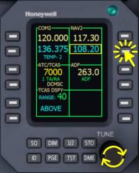
NAV2 Frequency
The frequency for the Ventura VOR is 108.20 MHz. To tune in this frequency:
- Click the second line select key on the right on one of the two Radio Management Units (RMU)
- Mouse over the inner or outer TUNE knob and use your mouse wheel to adjust the frequency. The outer knob steps full 1.0 MHz and the inner knob steps 0.05 MHz increments.
When the frequency of 108.20 is set in the cyan standby field transfer it across to the active field by clicking the first line select key of that RMU, the one just above the button just used.
NAV2 Course
The inbound course that we want to use is 255° but you can decrease that further if the course deviation indicator on the HSI is already left of the aircraft symbol. In that case use 240 or something like that, it is important that the needle is still right of the HSI center, otherwise we can't intercept the turn with the present heading.
To adjust the course of the NAV2 use the CRS2 knob (right CRS knob!)
- Mouse over the knob and use your scroll wheel of the mouse.
Change Autopilot Navigation Source
Each PFD has its' own navigation source, which can be FMS1, FMS2, NAV1 or NAV2. We select which one we want on our PFD with the onside display controller.
The autopilot then uses either the left or the right PFD's selected navigation source depending on the coupling arrow direction and we can change which one has priority with the XFR button.
This makes it possible to have the FMS on the left side and the NAV2 on the right side, like in our case, and then quickly switch from one source to the next.
Let me summarize the actions we did so far:
- Make sure the autopilot is not affected by our changes, it is currently in FMS, directed from the left PFD, that is fine. We could also go into HDG mode to be sure it doesn't suddenly make a turn when we change something.
- We set the NAV2 frequency of the Ventura VOR: 108.20,
- Set NAV2 as navigation source on the right PFD,
- Adjusted NAV2 course (255 or less)
And now we
- Set XFR arrow (identical to the coupling arrow) to the correct PFD (right side is the right side in this case) and
- Press the NAV button to arm the VOR capture
Currently the autopilot is still tracking our flight plan, time to change that. First we're going to change which PFD the autopilot is using, this will cause the autopilot to fall out of the FMS mode coming from the left side, back into its basic mode which is ROL. ROL means wings level below 6° of bank and bank hold above that. We should be careful switching nav-sources when our current bank angle is high, we have to make sure that we're not staying in ROL because the autopilot is just going to continue turning, no matter what :)
- A single click on the XFR switch on the FGC is enough to switch from left over to right side PFD.
Note - The coupling arrows on both PFDs (at the top in the flight mode annunciators FMA) as well as the green arrow next to the XFR button should point to the right now!.
Arm VOR Capture
Secondly let us arm the VOR capture, now that the autopilot has the correct navigation source.
- Click the NAV button on the FGC to arm VOR capture. VOR will be visible in white on the FMA
VOR Capture
Once the autopilot captures the VOR the FMA will display VOR in green. The screenshot shows the right side PFD.
Back To The Route
- Click the HDG knob
- Click the HDG pushbutton
- Use your mouse wheel over the HDG knob to turn the aircraft right, back onto the flight plan
- Click the XFR button again to select the left PFD and the FMS1 navigation source still selected on that PFD
- Click the NAV button to arm the FMS capture.
The FMS mode will engage when you are back on the flight plan.
Descent
Approach Briefing
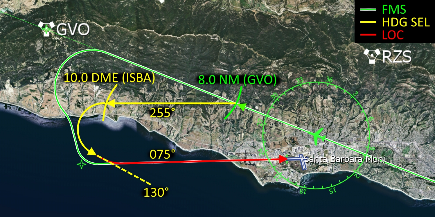
Shortly after Camarillo VOR (CMA) we are going to start our descent down to 3000 ft, descending in vertical speed mode (VS) at a rate of -2000 ft/min with 250 kts indicated airspeed. At 8.0 miles DME before the Gaviota VOR (GVO) we are going to break off from the flight plan and turn left to 255° and slow down to 180 kts. At 10.0 NM DME from ISBA we are going to turn left to 130° and intercept the localizer of runway 07.
We are going to fly the ILS 07 approach into Santa Barbara Muni (KSBA), the ILS frequency is 110.30 MHz, the approach course is 075°. The ILS localizer goes out to the open water of the Pacific Ocean, so no obstructions to worry about once we are established.
The airport elevation of KSBA is 14 ft and the runway is 6000 ft long (1828.8 m). On rollout we are going to turn right onto the first taxiway after the two intersecting runway.
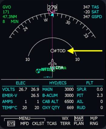
Top Of Descent
We are going to start our descent at the white #TOD marker on the map. Take a look at the MFD map display to see the position of the top of descent in relation to our aircraft.
Vertical Speed Mode
To start the descent we need to select a lower altitude and then press the vertical speed button on the Flight Guidance Controller (FGC). We're going to descent to 3000 feet and use a vertical speed of -2000 feet per minute.
- Move your mouse cursor over the altitude select knob (ASEL) and spin your mouse wheel to reduce the selected altitude displayed on the Primary Flight Display (PFD) to 3000 feet.
- Click the Vertical Speed (VS) button on the FGC
- Rotate the combined SPD/VS knob with your mouse wheel.
Note - Watch the vertical speed value on the Primary Flight Display (PFD) and set it to -2000 ft/min.
Transition Level
We are not below the transition level of 18,000 feet in the U.S. so we have to switch back to the local pressure at the airport. Since the pressure at the moment doesn't change yet there is no action required.
Set the recognition lights back on.
- Scroll over the RECOG light switch on the LIGHTS panel to set them to the upper position
10,000 ft
At ten thousand feet during the descent we are going to set the lights and seat belt signs back on.
- Over the L LDG or R LDG light switch scroll with the mouse to set both switches to the upper on position
- Repeat the process for the NO SMOKING/BELTS switch.
| Descent Checklist | |||||
|---|---|---|---|---|---|
| No. | Location | Panel Name | Action | Remarks | |
| 1 | Front Panel | PFDs, Standby ALT | ALTIMETER | STD 3x | Below 18k |
| 2 | Lower Front Panel | LIGHTS | RECOGNITION LIGHTS | ON | Below 18k |
| 3 | Lower Front Panel | LIGHTS | BELTS | ON | |
| 4 | Lower Front Panel | LIGHTS | LDG/TAXI | ON | Below 10k |
| 5 | Front Panel | EICAS/MFD | FUEL IMBALANCE | CHECKED | not modeled yet |
| 6 | Lower Front Panel | PRESSURIZATION | LDG ALT | SET | not modeled yet |
Approach Preparation
During the descent we are going to prepare the approach into Santa Barbara. We are going to fly in FMS on our flight plan up to 8 NM to Gaviota VOR (GVO) where we are going to turn left to 255° onto the downwind. By then we will have the approach set up fully so that we can switch our navigation source from FMS to NAV on our left PFD. We will slow down to 160kts and set flaps 5°. When we reach a distance of 10 NM to the localizer we will turn left to 130° to intercept it. The autopilot will intercept the localizer for us so that we can run final checks while it does that. At 200 ft above the ground we have to disengage the autopilot and land manually.
Note - This approach probably doesn't exist in the real world, I made this up for Aerofly FS training purposes.
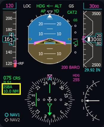
This may look complicated at first but it is actually really simple. All you have to do is look at the PFD, left of the HSI on the distance that is sown. The first time you will just have to press one button when the number is 8.0, the second time you just have to scroll over the heading select knob when the distance reaches 10.0. We will prepare everything in time, there isn't that much to do and we have a lot of time in between.
We are now going to prepare the ILS on the NAV1 and NAV2 receivers. For this we have to tune the receivers manually, set the navigation source to ILS1 or ILS2 and set the correct approach course.
ILS Frequency
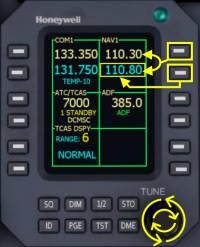
First we are going to set the frequency for the Santa Barbara ILS (ISBA), which is 110.30 MHz, on both NAV1 and NAV2 receivers.
On the left Radio Management Unit (RMU)
- Click the second right line select key to highlight the NAV1 standby frequency
- Use your mouse wheel over the fine and coarse TUNE knob to adjust the standby frequency to 110.30 MHz.
- Press the first right line select key to swap the standby and active frequencies.
Repeat for NAV2 on the right RMU, in exactly the same way.
ILS Course
Next we have to set both courses to 075. We are going to do this on the right side PFD so that we can continue flying in FMS with the flight plan and don't interrupt the autopilot.
First we select the NAV1 navigation source on the right PFD:
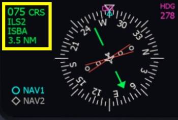
- On the right side display controller click the “NAV” button. The right PFD should now display “ILS1” with the identifier “ISBA” in the legend left of the HSI rose.
Now we can turn the right side CRS2 knob on the Flight Guidance Controller (FGC) to set the course
- Mouse over the right side CRS2 knob on the FGC and rotate the mouse wheel until the PFD displays 075 for the CRS.
Repeat for NAV2: Now switch to the NAV2 navigation source by clicking the NAV button of the right display controller again. Repeat the course with the same knob on the FGC.
Later on we are going to switch the left side PFD nav source to NAV1 and leave the source on NAV2 for the right side. Then by a single press on the APP button on the FGC we can arm the ILS approach. But we're not quite there yet, we have to descent a little bit further and position ourselves for the intercept.
Minimums
I'm going to assume an arbitrary 200 ft for the minimum descent altitude (MDA), the lowest barometric altitude to which we can descent without having the runway in sight. If we don't see the runway below an altitude of 200 ft (in this case) we have to go around and either hope for better weather or fly to an alternate airport, e.g. Camarillo.
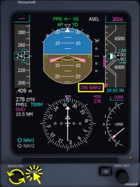
- Click the RA/BARO button twice
- Rotate the MINIMUMS adjustment knob next to it. Look at the highlighted area on the screenshot on your PFD and set a barometric altitude of 200 feet.
Approach Speeds
The approach reference speed (VREF) for our current mass of roughly 15,500lb and our landing elevation (below 4000ft) is
- VREF = 115kt (flaps 40, gear down)
A typical pattern in the Learjet 45 uses the following speeds:
- Gear up, flaps up: VREF + 40 kt ( = 155 kt )
- Gear up, Flaps 8°: VREF + 30 kt ( = 145 kt )
- Gear Down, Flap 20°: VREF + 20 kt ( = 135 kt )
- Gear Down, Flap 40°: VREF ( = 115 kt )
Note - The Flight Crew Operating Manual states that any use of flaps and spoilers at the same time is prohibited.
→ What does that mean for us?
When we turn onto the downwind leg of our traffic pattern we will slow down to 155 kts. We will then extend flaps to 8 degrees and slow down to 145 knots but only after the base turn. When we capture the glide slope we will select the gear down and set flaps 20° and slow down to 135 knots. At around 1500 feet we can select the final stage of flaps and slow down to 120 kts where the white “RF” is displayed on the PFD.
Setting Approach Speed (Optional)
For our own reference you can adjust the airspeed bug to 120 kts. To do so we cannot be in vertical speed mode, so you'll have to do this a little later, once we have leveled off, or you can press the VS button again to enter PIT (pitch hold) vertical mode for a second, set the speed, then come back to vertical speed mode.
When you are not in VS mode you can adjust the selected speed easily:
- Mouse over the speed knob and spin your mouse wheel to select the speed. The selected value is displayed in the upper left corner of the primary flight display (PFD).
| Approach Checklist | |||||
|---|---|---|---|---|---|
| No. | Location | Panel Name | Action | Remarks | |
| 1 | Front Panel | PFD | LANDING DATA | SET | VREF adjustment not implemented yet |
| 2 | Front Panel | PFD | MINIMUMS | SET | |
| 3 | Front Panel | n.a. | AVIONICS AND RADIOS | SET | |
| 4 | Lower Front Panel | PRESSURIZATION | HIGH FLOW | OFF | not implemented yet |
| 5 | Pedestal | ENGINE | ENG SYNC | OFF | not implemented yet |
Approach
Alright, we have everything set up that takes a bit of time. You should be abeam the airport right now as seen on the approach diagram. Now the fun can begin, we're going to fly the pattern around KSBA. Continue flying straight for now.
Here is the approach diagram from earlier again:
Preparation For Downwind Leg
Select the heading for the downwind leg, 255°. Do not enter the heading select mode yet, only turn the knob :)
- Mouse over the HDG knob and turn it by rotating your mouse wheel.
- Rotate it until you have a selected heading of 255° displayed on the PFD.
Turn Downwind
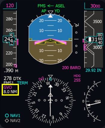
When the primary flight display (PFD) shows a distance of 8.0 nautical miles (NM) remaining to Gaviota (GVO) as shown here:
Then activate the heading select mode.
- Click the heading push button on the FGC.
Reduce Speed
Slow down to VREF + 40 knots = 155 kt but no slower than that.
- Adjust your throttle input and monitor the speed.
Switch NAV-Source NAV1
Switch over to the NAV1 navigation source on the left PFD. We already prepared the ILS1 earlier on this navigation source.
- Click the NAV pushbutton on the left display controller
Extend Flaps To 8 Degrees
We are below the maximum extension speed for flap 8° which are incredible 250 knots in this aircraft. Hence the name LearJET I guess :D
- Use your scroll wheel over the flap selector or press your assigned key command to extend the flap, default key is “f”.
Arm Approach
We are about to turn left onto the base leg, we can already arm the localizer and glide slope capture now, or after the turn. To arm the ILS approach mode:
- Switch do the ILS navigation source, which we already did,
- Click the APP button on the FGC as highlighted on the screenshot.
Wait For Turn Base
At 10 NM DME from ISBA (as seen on the screenshot) or a bit later (11, 12 or 13 NM should work just as well) turn left to 130° to intercept the localizer. 10 miles is the earliest you can make this turn, that would be the shortest time. But to be sure everything goes as planned count to 10 and then start turning.
Please note - If you are not yet leveled at 3000 feet yet you should also extend further outward until you see the green glide slope triangle between the attitude indicator and altitude tape moving.
- Mouse over the HDG knob and turn it by rotating your mouse wheel.
- Rotate it until you have a selected heading of 130° displayed on the PFD.
Note - Make sure you keep your speed at or above 155 knots, adjust your throttles in the turn as needed. When you fly too slow at this point you may end up above the glide slope. You can notice this when that GS remains in white on the first line on the PFD and the aircraft doesn't seem to descent on it's own and you can see the runway far below you. In this case just use heading select again, as shown before. Turn back to 255°, speed up to 180 knots, extend the downwind a bit further (beyond 10.0 DME), and then just try again, no big issue!
On the approach diagram we are now flying the 180° turn towards the dashed line.
Localizer Capture
The Flight Guidance will capture the LOC and very shortly after the glide slope (GS) but only in that order. The glide slope cannot be captured before the localizer even though you may already be established. On the screenshot below I want to raise your attention towards the highlighted areas.
- At the top of the display you can see the Flight Mode Annunciator (FMA) which shows the localizer and glide slope capture in green. This indicates that the aircraft has captured the ILS and will descent down to the runway.
- To the right of the attitude indicator you can see the glide slope indicator. On the screenshot the green glide slope triangle is already perfectly centered. If the diamond is below the center at this point and GS does still show in white you can attempt catching up with the glide slope using vertical speed mode (VS) as shown earlier and a rate of 1500 ft/min. Or just use heading select and a heading of 255° degrees and try again.
- The arrows indicate the movement direction of the deviation indicator. Once the deviation hits zero you are exactly on the extended runway centerline.
Reduce Speed, Flaps 20
Now that the localizer and glide slope are captured idle the thrust and slow down to VREF + 30 knots = 145 kt. When you reached 145kts extend flaps to 20° and continue to slow down to 135 kts (VREF + 20 kts).
To extend the flaps
- Rotate the mouse wheel over the flap lever.
Gear Down
At around 2000 ft extend the landing gear to help slowing down the aircraft.
- Click the landing gear lever or use your key assignment (default key “g”).
Flaps Full, VREF
Set full flaps now and decelerate to 120 knots.
Before Landing
Arm Spoilers
During landing the ground spoilers will automatically deploy and dump excess lift to increase the wheel friction and improve braking action. The auto spoilers have to be armed for this, like we did before takeoff.
- Click the spoiler lever to set the spoilers to the armed position.
Note - On the EICAS in the Crew Alerting System (CAS) window a “AUTOSPLR ARMED” text will appear in white.
| Landing Checklist | |||||
|---|---|---|---|---|---|
| No. | Location | Panel Name | Action | Remarks | |
| 1 | Quadrant | SPOILER | AUTO SPOILER | ARMED | |
| 2 | Lower Front Panel | GEAR | AUX HYD | ON | not modeled yet |
| 3 | Lower Front Panel | GEAR | GEAR INDICATION | DOWN 3x green | |
| 4 | Lower Front Panel | LIGHTS | LANDING LIGHTS | ON | |
| 5 | Quadrant | FLAPS | FLAP LEVER | DOWN | Below 150 kts, confirm down position on EICAS display |
| 6 | Glareshield | FGC | YAW DAMPER (YD) | OFF | |
| 7 | Front Panel | EICAS/MFD | SYSTEM PAGES | SUMRY and FLT | or vice versa |
Final Approach
The one thing we have to do at the moment is maintain our speed at 120 knots because the autopilot won't do that for us without autothrottles. Get ready to take over controls.
Autopilot Off
Disconnect the autopilot before reaching 200 ft above ground. The autopilot is only certified for CAT 1 approaches.
Go Around
If you have to go around
- Press assigned TOGA button, fly manually
- Advance thrust levers to go around (full thrust) if desired
- Reduce flaps to 8°
- Select the landing gear up when the vertical speed is positive
- Pitch to maintain 120 knots with flaps 8
- Then accelerate to 140 knots or faster and retract flaps
- Disarm spoilers
Then turn left to 255° and repeat the approach procedure.
Landing
Flare
At 55 ft radar altitude (the white boxed number on the PFD in the attitude indicator, at the bottom) gently move your thrust levers to idle. Counter the pitch up tendency due to the engine thrust change and steer the aircraft a bit towards the ground. Softly flare the aircraft, due to its low wing it has a lot of ground effect, not much pull up is required.
Touch Down
Check the spoilers extend, on the EICAS you can see the spoiler position going up and in the CAS you can also read the text “SPOILERS EXT”.
Rollout
Activate the thrust reversers. Use your assigned controls for this. You may use the thrust reversers up to 40 knots airspeed in this aircraft.
Slow down with the brakes and try to vacate the first taxiway after the two runways.The best visual clue are the markings on the runway. We want to take the exit just before the large solid white rectangles (beginning of the touch down zone from the opposite direction).
After Landing
Lights Off
When you turn off the runway turn off the landing and strobe lights.
- Mouse over the landing light switch and rotate your mouse wheel to set them to the OFF position.
- In the same fashion, set the REGOCnition light switch to OFF
- And set the BCN/STROBE light to BCN.
ATC/TCAS Standby
On the Radio Management Unit set the ATC/TCAS to standby.
- Click the fourth left line select key from the top
- Rotate your mouse wheel while pointing at the inner part of the TUNE knob
Flaps Up, Retract Spoilers
- Select the flaps up by either pressing your assigned key or button multiple times or by rotating your mouse wheel over the flap lever as shown earlier.
- Click the spoiler lever to set it to the retracted position and disarm the auto spoilers.
Flight Directors Off
We can now reset the flight directors and clear any modes in the Flight Mode Annunciator (FMA) on the PFD.
- Click the left FD1 button and the right FD2 button to reset the flight directors
Note - When the autopilot is engaged in flight, if you press the flight director key on the side the XFR arrow points to, the flight guidance modes will be reset to ROL and PIT basic modes. If you press the opposite side the flight directors on that side will disappear from the PFD.
Now we reached a similar state compared to how we found the aircraft at the beginning of the tutorial.
| After Landing Checklist | |||||
|---|---|---|---|---|---|
| No. | Location | Panel Name | Action | Remarks | |
| 1 | Front Panel | RMU | ATC/TCAS | STANDBY | |
| 2 | Lower Front Panel | LIGHTS | LANDING/TAXI LIGHTS | TAXI | |
| 3 | Lower Front Panel | LIGHTS | RECOGNITION LIGHTS | OFF | |
| 4 | Lower Front Panel | LIGHTS | BEACON/STROBE | BEACON | |
| 5 | Quadrant | SPOILERS | SPOILER LEVER | RETRACTED | |
| 6 | Quadrant | FLAPS | FLAP LEVER | UP | |
| 7 | Pedestal | WEATHER RADAR | WX MODE | STANDBY | |
| 8 | Front Panel | STANDBY INSTRUMENTS | STBY ATTITUDE INDICATOR | CAGE | Not implemented yet |
Taxi To Parking
Continue straight on the taxiway. You'll find plenty of aircraft parked South of the building with the red roof, find a nice spot and set the parking brake.
Final Words
Let us quickly summarize the flight that we did. At Bob Hope we prepared the aircraft for takeoff, taxied to the runway and used the FMS to guide us along the route. If you did the little sight seeing tour at the beginning I hope you got to see the Hollywood sign or at least now know where it is located. In the air we demonstrated the VOR capture and descended in vertical speed mode. The Learjet also has VNAV capability for the descent if you want to try that out, check out the Q400 tutorial, where we describe a VNAV descent for a very similar autopilot. Throughout the flight we had to manage the throttle ourselves, because the Learjet's autopilot isn't equipped with auto throttles. At the end we did a basic pattern in heading select mode and intercepted the ILS into Santa Barbara. I hope that this part wasn't too complicated and that you managed to to fly the approach.
Hopefully this tutorial provided you with enough information to that you can manage your next journey in this aircraft all by yourself. You could retry the tutorial flight with the VOR capture and the Hollywood sign next to gain a bit more understanding about the navigation source selection to use it to your benefits. Or you could continue the flight northbound to San Francisco or South towards San Diego or Catalina.
If you enjoyed following this tutorial, maybe you might also have fun trying out the Dash8 Q400 flight tutorial next? There are plenty of similarities between their autopilots, the navigation source selections among other things. Once you understand the way the autopilot works in either of the two aircraft you will probably understand the other autopilot as well.

