Posts by qwerty42

    I'm not 100% sure, but I think your background image has been included in one of the items you exported from AC3D. When you export your model from AC3D, you only want to export (a) your runway and the runway outside area, and (b) your decals. Those should be exported to a file called ybbn_rwy.tgi for the runway/outside area and ybbn_decal.tgi for the decals.

    The object that contains the background image in AC3D should not be exported, it's only there as a reference for you to build the runway on top of. The specific reason for the error is that the content converter only supports texture files that are square and max dimensions of 2048x2048, but regardless you want to make sure you're not including the background image object in your export from AC3D.

    ok thank you Querty, if it wasn't for the time you took to explain it in such detail i would not have got here, but the runway finally is showing up, decals are missing but that is for another day

    thanks again, i will need to record all this so i do not forget the steps !

    Nicely done! The decals should be an easy fix. Things to check: (1) Did you export the decals from AC3D to a .tgi file? You have to export them to their own .tgi file just like you export the runway. (2) Do you have an entry in your .tsc file for the decals? It'll be in the Objects section of the .tsc file and will look like this:

    <[tmsimulator_scenery_object][element][1]

    <[string8][type][decal]>

    <[string8][geometry][ksmn_decal]>

    <[tmvector3d][position][-113.881706 45.122031 0]>

    >

    Instead of "ksmn_decal", that should be the name of your .tgi file for your decals. And the coordinates entered next to [position] should be the same as what you entered for your runway/airport (these are the coordinates of your reference point).

    Check those two things when you have time again and let me know if it fixes it or not.

    Hi Clayton,

    He actually mentions it at 3:49 in his "Background image for airport design using AC3D" tutorial here:

    External Content www.youtube.com
    Content embedded from external sources will not be displayed without your consent.
    Through the activation of external content, you agree that personal data may be transferred to third party platforms. We have provided more information on this in our privacy policy.

    You can just select all of your objects (background, runway, decals, etc) and then rotate everything 90 degrees first. Then, rotate it the other direction 27 clicks (I'm guessing you had it set to 1 degree per click?) and you should have it lined up like my image.

    After that, double check and make sure your crosshairs in AC3D are still lined up over your original reference point in the background image. If they aren't, select all of your objects together, and drag them until the crosshair is back on top of your original reference point location on the background image.

    Then (assuming you're finished with the model) you should be able to export your runway and decals and then convert them for AeroFly.

    I re-read and saw you said you were also stuck on rotation. Again, it seems confusing but it's actually very simple. When you're modeling your airport, rotate the background to any direction that makes it easy to place your mesh and shapes. Then, when you're done with the model and ready to export it, you need to rotate everything so that north on your background image points to the right side (+X axis) in AC3D.

    So for the airport you're working on now, before you export it, it should be facing this direction in AC3D (along with all your objects/surfaces/decals etc.):

    Hi Clayton,

    That looks good so far. Let me explain the reference point thing a little further--I think once you understand its purpose and how it works, it will be easier to deal with.

    The "reference point" is just an arbitrary location on your background image. It can really be anywhere you want, but wherever it ends up, you need to enter the lat/long coordinates of that exact spot into your .tsc file.

    In other words, the reference point is the latitude/longitude coordinates of wherever the crosshairs in AC3D are shown when you export your airport files. You can even change your reference point to a different location if you want: just drag your objects around in AC3D wherever you like (just make sure to select all and drag them all together), until the crosshairs are on a spot you can easily identify on the background image. Then just open up google maps, find that exact same spot on the satellite view where your AC3D crosshairs are, zoom way in, click it, and copy the coordinates. Those are the coordinates you then need to place in your .tsc file.

    In Rodeo's video tutorial he explained a great way to do all of this so you don't actually have to understand exactly what the reference point's meaning really is, and that works well if you're careful not to move your objects away from that original reference point. (EDIT: Actually his video explains exactly what I said here quite clearly, sorry about that! I must have had it confused with something I read in a different tutorial. See 4:20 to 5:30 in his video here.) What I just described above lets you use anything you want as your reference point, you can even move it somewhere else if you'd like. The important thing is just that, wherever the crosshairs end up on the background image in AC3D, you need to make sure the coordinates you enter in your .tsc file correspond to that location.

    Even if you're really careful with your rotations when modeling the airport, you might end up with the reference point shifted to a different location after the final rotation to align your airport so that North points to the right. This is because it rotates about the geometric center of the shapes you're rotating. This means that if you add any objects that increase the outer size of your airport/mesh/etc. after the first rotation, when you rotate it back it will rotate around a different point, causing the crosshairs to move away from your original reference point. It's easy to fix though: you can then select all of your objects together and drag them so the crosshairs are back at your original location on the background image, or you can drag them to somewhere new and then use google maps to determine what the coordinates are of that location, as I described above.

    I hope that wasn't too confusing. Maybe I'll make a video to describe this too. I think showing examples of this rather than trying to type it out will make it a lot clearer!

    Hi Clayton, I got it working for you. There were quite a few things I changed, so I tried to keep a list as I went. I think this is all of them.

    Here is the folder you sent me, with the corrected files inside: https://www.dropbox.com/s/iahpsv8p24eqhi9/ybaf_rwy.zip?dl=0

    And here are the already-converted files that you can load directly into Aerofly if you want: https://www.dropbox.com/s/1j0cm7qymgmyer8/converted.zip?dl=0

    So, to the list of changes:

    (1) The reason you had the sunken ground is because the elevation was incorrect in your .tsc file. This is the line that says: <[float64] [height]... I think the value you were using was in units of feet, but it actually needs to be in meters for this file.

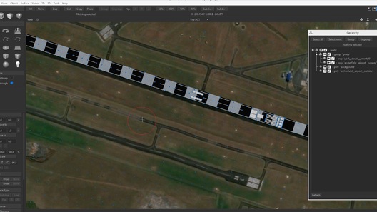
    (2) The coordinates in your .tsc file did not match the actual reference point in your AC3D model. In the model your reference point was here (I circled it in red to make it clearer, it's the small white crosshairs):

    But, the coordinates in your .tsc file actually refer to the spot marked here by the red pin:

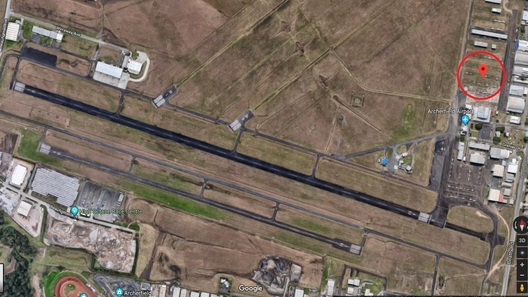
    There are a lot of ways this can happen: if you accidentally used one of the corner point coordinates from FSET instead of the center point, or if you accidentally moved all of your objects in AC3D (easy to do unintentionally). I've also noticed that if you're rotating objects, AC3D rotates about the geometric center of ALL the items you are rotating -- so, if you rotate some objects, but then add more objects that extend beyond the original bounds of the first rotation, when you rotate it back to where you started it will rotate around a different center point. Because of this, I find it easier to just pick your reference point after you're all done with your airport modeling (you can select all of your groups/objects and then drag them until the crosshairs in AC3D are lined up to the reference point you want to use), then figure out what its coordinates are by clicking that same point in Google Maps, and lastly use those coordinates in your .tsc file.

    (3) The airport was also 90 degrees off from the direction it needed to face. This is a bit confusing, but the x-axis in AC3D (which points toward the right of the image) corresponds to North. So when you're all done modeling your airport and you rotate it before exporting, the north direction of your airport needs to point to the right in AC3D.

    (4) There were a number of other errors in your .tsc file that would have caused other issues: the entry to convert your decals was missing, there was an extra ">" character that would've caused an error, and I commented out the cultivation entry at the end because I don't think you have any cultivation files (I don't know if it causes an error or not to include it even if it doesn't exist, but I assumed so).

    (5) There was a file path error in your .tmc file that prevented it from converting. I think one of the other users that was helping you entered their own file path info, so it was giving an error. I edited the .tmc file so it just looks for the files it needs it the same folder where it already is, which fixed that error.

    (6) The groupings in AC3D were incorrect -- the decals were grouped with part of the runway objects, and another piece of the runway was by itself outside of a group. I fixed all the groupings, so just open up the new file I made (ybaf_fixed.ac) and look in the Hierarchy View to see how it needs to be named & grouped. You will have problems when you export and then convert the .tgi files if you don't keep the naming & grouping structure like this.

    (7) I swapped out the texture file for the decals to one that works correctly with transparency (still don't know why that error is happening but it seems like AC3D doesn't like alpha channels in .tif files?). Also re-mapped your runway texture so it repeats and keeps the resolution of the texture crisp.

    I hope that helps! If you want to further edit the airport (the decals still don't really match the real runway, nor do the numbers), you can open the ybaf_fixed.ac file and start re-arranging things as you'd like. Then just export the groups again as Rodeo shows in his tutorial video, and lastly convert them by right-clicking the content_converter_config.tmc file and telling it to run with the Aerofly FS2 Content Converter.

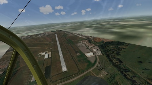
    Here's a screenshot of how it looks right now (I only geoconverted a small area around it):

    Thanks qwerty42 - this is great stuff and very much appreciated. I've read it a few times and am trying to follow it now. I'm not sure what you mean by innermost vertices though? So far I've made a large mesh that covers the background image, and cut out a section that just spans my two overlapping runways. By "innermost vertices" do you mean the outside vertices of the inner cut out mesh?

    Also am I limited to the resolution of the mesh when it comes to aligning it with the background image?

    Yep, you're correct on what I meant by "innermost vertices." If a picture is worth a thousand words, a video is worth at least a thousand pictures, so I made a screencap of the whole process for you. It's not as good as the stuff Rodeo makes and there's no audio, but hopefully it helps:

    External Content youtu.be
    Content embedded from external sources will not be displayed without your consent.
    Through the activation of external content, you agree that personal data may be transferred to third party platforms. We have provided more information on this in our privacy policy.

    A few important notes:

    -When you're selecting stuff, there's an option on the left side called "Select through." The setting of this is really important when you're selecting things, so pay close attention to what I have it set to in the video. If you don't have it enabled when grabbing all your runway vertices, it might not select all of them if they're packed close together like mine. However, it can also create issues with selecting what you intend to select in the 3D view, as you'll see at the end of my video when I was trying to correct the surface normals...

    -When you merge the new runway cutout surfaces with your larger outside mesh, the object you select FIRST will be the name it keeps. So if you already have it named and grouped like I did, make sure to select the keeper first before doing the merge.

    -You will need to flip and then unify the surface normals so they all point 'up.' I showed you how to do this at the end of the video also. Note that I made a mistake at the very beginning -- I still had "select through" enabled, and when I intended to select the surface under my mouse cursor, it for some reason selected a surface off-screen and I didn't notice. Because of this, I accidentally flipped the normal on a surface I didn't intend to flip. You'll see me hunting around for it at the end and finally finding it and fixing it.

    -When you choose "Unify normals", it will set all connected surfaces so their normals point the same direction as the SINGLE surface you've selected. So if you have several contiguous areas like I did, you'll have to repeat this operation on all of them. If you don't do this, you'll have huge gaping voids in your terrain that cause some really interesting and violent crashes if you touch them at all ;)

    There may be a better way to do this--I'm not sure. This certainly isn't that simple and it creates a really ugly mesh if you have used curves and splines to define your runway like I did, but Aerofly doesn't seem to mind about the mesh ugliness because it's only using this to determine where the non-runway terrain ends as far as I can tell. I also tried using the Boolean operations and the knife command after extruding the cutting surfaces, as well as the fill holes command, and none of them could quite make this work without other issues.

    Rodeo - Just a teeny request for the bottom of your multi-page "to do" list. Can you do another video tutorial showing a more advanced form of runway mesh cutout? I couldn't find out any more about using the knife or vertex picking. There's a lot of youtube about AC3D but they generally seem to be about creating new objects and not overlaying things onto photo scenery and aligning object/vertices to it.

    As well as the criss-cross runway problem I just made a second runway on a different airfield but found that the 45m mesh I created to match the runway width was a poor fit lengthwise, so either I chop off a chunk beyond the runway or I have some background runway markings emerging beyond my created runway.

    As I say a request for the list. I'll have some fun now adding objects to my airports.

    This was definitely the most difficult thing I encountered with the runway I modeled. I tried the knife and also using Boolean combinations to do the cutting, but never got a result that I was perfectly happy with. Perhaps I was doing something incorrectly, but I always ended up with really tiny gaps between the 'outer area' and the runway which created open slivers when loaded into the game.

    I can explain better in a day or two when I have more time, but what I finally got to work was to cut out an area of my 'outside' mesh around the runway. Then, selecting the innermost vertices of this cutout, as well as all of the vertices of my runway, I then went to Vertex > Create 2D Mesh > XZ (Plan). You will end up with a triangular surface mesh that connects the all the vertices, meaning you will need to then do a shift-select to grab all the ones where your runway is and delete them to create the cutout. This was the only relatively easy way I found that gave perfect vertex-to-vertex correspondence so that there were no sliver openings when loaded into Aerofly.

    Also note, to make this work well, you need to have clean surfaces for your runway meaning no overlapping surfaces, and portions of surfaces that connect should have their vertices snapped to each other and then merged with the Vertex > Weld command. (It doesn't matter if your decals overlap, just make sure the runway object surfaces do not.) Another thing to be careful of is make sure that all your surface normal point the correct direction -- you can check this by turning on "Normals" in the 2D and 3D menus, and then looking at the different viewports. The pink lines (those are the normals) should come 'up' from your runway, not point below it. If it's hard to see the pink lines, go the the settings menu, to the graphics tab, and then change "Size of display normals" to a higher value, e.g. 10.

    Here's a picture of my mesh which may help explain the above. It does get a bit tricky, but I think I have tried just about every possible way of doing this now and this seemed to be best unless your runway geometry is very simple:

    I know some of the devs keep an eye on this forum, so I just wanted to say thank you, and what an amazing job you've done with Aerofly. I play in VR on an Oculus Rift, and every time I get into the cockpits of these planes and jets I am just blown away by the visual quality and attention to detail. I don't think a single other VR title I own even comes close in the realism of Aerofly. Whoever is the person(s) making your aircraft models is truly an artist, and having done some of that work myself before I know it takes not just an incredible amount of skill and patience, but also an artistic eye to make things look that good.

    Also, the performance is incredibly good for such a visually detailed sim. I can run with all settings on ultra at 90 fps in VR with only a GTX1060 3GB card. That's astonishing, considering I also play IL2 Sturmovik and even with the lowest possible settings it's usually dropping to 45 FPS with framewarping on the Rift.

    Lastly, the flight physics are very good, and getting better with each update it seems. For example, I looked up the pilot's training manual for the P38 (published 1945!) and was really surprised by how a lot of things I thought were flaky physics are actually real characteristics of the plane, like the wing's tendency to pitch downward at lower speeds requiring the plane to be lifted off the runway with a lot of elevator during takeoff. All of the approach and landing speeds were dead on as well, and it even starts buffeting with loss of control surface effectiveness near transonic/compressibility speeds in a high speed dive. I can't help but wonder how many other people's complaints about some of the flight physics are actually just real characteristics of the real-life aircraft? ^^

    Actually one other point of praise, making your SDK available and working on all the documentation and tutorials for us to use them is really great. I know there's still more to be done there to make it simpler for others, but just using the current offerings I have been able to add highly detailed scenery for my hometown and just this weekend build a detailed airport model as well. I hope the community around this sim continues to grow and I won't be surprised to see it on top of all the rest in the not too distant future!

    A couple screenshots of my hometown scenery and airport I added:

    Thank you so much for taking the time to put together these tutorials Rodeo. I had a lot of the same issues the others had, but was able to to make a really nice runway and airport layout for my hometown in the rocky mountains of Idaho. I also was able to make my own custom textures and decals after seeing how it was done, and the final result is really quite good.

    Did anyone figure out the problem with the decals and the alpha channel not working correctly for the .tif files? I had the exact same problem; AC3D was displaying the texture but not doing anything with the alpha channel. I opened the tif in Photoshop and confirmed the alpha channel was indeed there, and only after I re-saved the texture from Photoshop by discarding layers and checking the 'preserve transparency' box did it actually work in AC3D.

    It seems pretty weird that some installations of AC3D would work with the alpha channel in a .tif while others do not... ? Anyway, for anyone having this issue, I can send you the new file I saved that should work so your number decals appear correctly if you'd like.

    A few screenshots: