Posts by turman

    Thanks Antoine for your post.

    What looks crazy for me is that you have the spike issue even if you disable the Swiss DLC mesh.. and also your own mesh ?!?

    The inefficiency of the flag for masked image creation is also surprising...

    Geoconvert has a lot of hidden secrets !!

    If I get the Spike-Fields, it is usually the wrong modifications or export from gimp. I also use the SRTM 1°Arc sources from the IPACS-wikipages. These are already in geoTiff format, so I do not need to convert the sources into geoTiff, they already are.

    Interesting, could you please post the link ? I tried "SRTM" on the wiki search but without any result...

    Czech Republic Meshes working well together with the standard-Mesh so far. I always compile whole tiles without masked files as a result and go from Level 9 to 11. I don't do Level 7 and 8. The borders of the tiles are looking ok at the moment. So I don't see why I should do 7 to 8.

    (Well, I compile the whole region and just put the right files for the specific tiles I am working on into the scenery.)

    I'll try to build the mesh with levels 9-11 only, but I'm not optimistic because the issue was present whatever the distance between the camera and the impacted aera...

    I had the same spikes issue when generating a 5m mesh partly overlapping the Switzerland DLC

    BTW, this caused some mess in my photo scenery display priority, even after totally deleting this mesh attempt.

    I had no problem compiling 5m DEM mesh in other zones like Courchevel or Paris, ie. without overlap with Swiss DLC.

    A place like Nice should however be in the same category...

    So for you Antoine we can have the issue if we build a mesh over an existing mesh, but not the default mesh.

    I wish it was like that but unfortunately in my case it does not work :(

    But I should dig a little more these masks stories, maybe it's the clue !

    Thanks for your responses, Vincent.

    It's strange, all my last posts have been merged with the post #12 ! I guess this is automatic feature of the forum but it's not very handful because it prevents others from knowing that there has been a new post.

    Anyway I'll be curious if people have ever encountered this kind of conflict problem with the base mesh.

    If the problem concerns all the DEM files provided by J. de Ferranti I imagine that other people have already succeeded, or at least tried ...

    Thanks Rich for your try.

    We could imagine the DEM file of Nice has something wrong in its content but I have a very similar issue with the DEM files from de Ferranti as well. And these files are already in WGS84 so issue is not linked to a wrong conversion / reprojection !

    On QGIS we can see the 2 TIFF have correct "Z" values:

    • Nice: from 20 to 2649 meters
    • N43E007 (de Ferranti): from 0 to 1456 meters

    As you said it is like a wacky factor is applied to the Z values, but why ???

    BTW your screenshot is a bit different from mine: mountains seem less high and around them there is that surface without any relief.


    After tons of attempts I tried to rename the elevation directory provided by default with AFS2 in order to disable it and then my mesh is finally displayed correctly ! :huh:

    The problem therefore seems to come from a conflict with the base mesh, any idea why ?


    Note that the previous screenshot is the mesh based on Johnathan de Ferrati's tile (30 meters resolution). With the mesh based on the open data DEM of Nice (5 meters resolution) I still have the same issue than before, even with the base mesh disabled, but I have to retest to be sure.

    I'm pretty sure South West and North East corner is correct because it is a similar system like U-V coordinates, but if both work then if obviously doesn't make a difference.

    But in my case both don't work :(

    If I have time I'll try with another DEM file to check if the issue is related to file itself or not.


    So I tried with N43E007 tile from Jonathan de Ferranti's website (embeded SRTM 30 meters).

    This time the SRS of the file is EPSG:4326 so no conversion is needed:

    But sadly the result is very similar:

    There must be something obvious wrong but I do not know what X(

    I've tried the two ways of setting coordinates in the TMC file.

    NW corner and SE corner:

    Code
    <[vector2_float64]     [lonlat_min]   [6.999861111111112 44.00013888888889]>
    <[vector2_float64]     [lonlat_max]   [8.00013888888889 42.999861111111116]>

    SW corner and NE corner:

    Code
    <[vector2_float64]     [lonlat_min]   [6.999861111111112 42.999861111111116]>
    <[vector2_float64]     [lonlat_max]   [8.00013888888889 44.00013888888889]>

    And my TFW file is:

    Code
    0.000277778
    0
    0
    -0.000277778
    6.999861111111112
    44.00013888888889

    I have tried MultiSpecW64 and the values are the same as in QGIS (as expected).

    I also tried to first convert the TIF image from its original SRS (EPSG:2142) to the standard one (EPSG:4326) *before* to open the "Save as" window of QGIS. That way the values are directly in EGPS:4226 (ie. no need to change the SRS in the dialog box). With that method the north/south/east/west values are slightly different but the pixel size was totally different from the previous ones (X and Y are now equal which was not the case before). Anyway the result is result is almost the same: the impacted surface is not exactly the same but I still have mountains with heights around 50 kilometers :(


    strictly speaking

    min should be lower left corner so South/West corner (lowest lat and lon)

    and max should be North/East corner (highest lat and lon)

    Are you sure Jan?

    The WIKI says Max = SE corner

    https://www.aerofly.com/dokuwiki/lib/e…cenery_creation

    It would be nice the clarify it.

    It's true that "lowest lat and lon" means South West corner.

    But in the AFS literature (wiki and forum) it looks it is the North West corner which must be used.

    And in my case I even don't see the difference when I changes the values (but maybe it's linked to another issue).

    In fact my original values were like that (with NW corner and then SE corner):

    Code
    <[vector2_float64]     [lonlat_min]   [6.743398875698556 44.36568831142908]>
    <[vector2_float64]     [lonlat_max]   [7.467846368136574 43.63047716301322]>

    But the result was exactly the same (which was a bit surprising for me).

    @flightxtreme: your tool looks interesting and I'll give a try tonight but the values visible on your screenshot are the ones with my DEM file ?

    Hello,

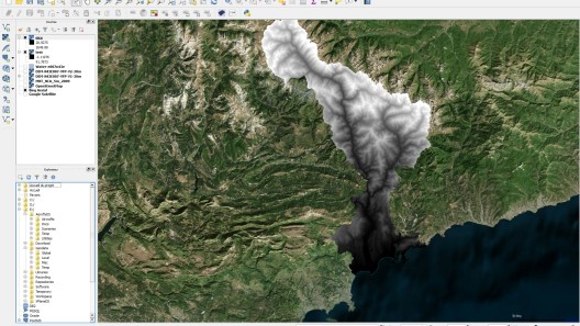
    I'm trying to build a mesh for the area of Nice, France with a DEM of 5 meters resolution from the open data portal of the Municipality.

    Here is the DEM converted to TIFF in QGIS:

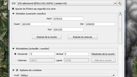
    Here are its coordinates in its original CRS:

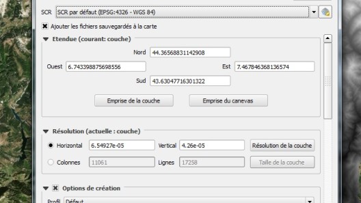
    And here they are in the standard CRS (EPSG:4326):

    My TFW file:

    Code
    0.0000654927
    0
    0
    -0.0000426
    6.743398875698556
    44.36568831142908

    My TMC file:

    But the result is not perfect as you can see :)

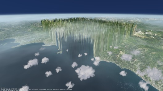
    The issue is not only about the heights, the impacted surface is not really correct too...

    Any idea of what's could be wrong in my settings ?

    Note that I have to close manually the Geoconvert window at the end of the process (100% of the tiles are generated) but this can be considered as "normal" as said in another topic.

    I'd would rather see an error with the pixel size (line 1 and 4 in the TFW file).

    Thanks for your help, Vincent.

    Thanks Antoine for your reply. Indeed it looks better to have unique indexes, at least for debuging purpose...

    About the end of the Geoconvert process: I'm still surprised.. everyone really needs to close manually the Geoconvert window ??? If yes it sounds crazy that IPACS has not solved that issue yet. And at least we should have the green message saying the process is well finished (like it is when Geconvert is launched by Aeroscenery for building orthos).

    Hmm there is that note in the PDF:

    Quote

    Caution: after job completion, Geoconvert unfortunately doesn’t close without a manual
    action, and the tool doesn’t seem suited yet for several parallel processes.

    So apparently it's "normal" that my Geoconvert process never finishes and it should not be the reason of my mesh build failure...

    I have a small question: in TMC files I guess that elements of lists must have an unique index. In your doc it's the case in the TMC sample for geconverting ground textures but it's not the case in the TMC sample for geoconverting elevation data: the indexes of each <[tmcolormap_region][element][x]> are not incremented and always set to 0. Is it normal ? It looks for me like an error.. but apparently it does not bother Geoconvert and there was the same "issue" in the TMC sample of the Qwerty42's tutorial...

    I've several issues with my mesh build but apparently it doesn't change anything if the elements indexes are unique (incremented) or not (always set to 0) in the TMC file.

    I have to create a separate thread for my issues but right now I have another small question: why the Geoconvert process never finishes ?

    When 100% of the tiles are generated it happens nothing, the CPU usage slows down (from 50% to 25%) and nothing is written in the logs. I need to close manually the Geoconvert window or kill the process. Note that when Geoconvert is launched by AereoScenery I have to close manually the windows too, but at least there is a green message saying the process is well finished.

    I have a small question: in TMC files I guess that elements of lists must have an unique index. In your doc it's the case in the TMC sample for geconverting ground textures but it's not the case in the TMC sample for geoconverting elevation data: the indexes of each <[tmcolormap_region][element][x]> are not incremented and always set to 0. Is it normal ? It looks for me like an error.. but apparently it does not bother Geoconvert and there was the same "issue" in the TMC sample of the Qwerty42's tutorial...

    Yeah very nice job Antoine, many thanks ! :thumbup:

    This document is more than useful knowing that the Wiki is not quite filled for the moment (that said it would have been even nicer IMHO to have all this valuable content directly in the Wiki itself instead of having it in a separate PDF).

    Thanks Vogel, I don't have the time yet to play with your program but it looks very interesting.

    And you gave me the infos I was looking for: ~150 meters for the default mesh resolution.


    You said 150 meters because the AFS level is 7 by default for the whole globe (and level 7 means ~150 meters per pixel) but actually the resolution of the used elevation data itself could be be less, right ?

    In fact I don't understand what the AFS levels exactly are. It sounds for me they are the different levels of details that the AFS 3D engine can support but I'm a bit confused, especially with the difference with the zoom levels (for orthoimagery). For the last ones it is not the level 7 but the level 10 which corresponds to 150 meters / pixel (at least for OSM but it's standardized).

    By default Aerofly FS uses 10m mesh accuracy for regions where we added airports. So this basically means all of the West Coast in the USA features 10m. The other parts of the world usually only have a lower resolution to reduce the overall size on disc. Aerofly FS would in theory support 2.5m mesh accuracy, but elevation date is hardly accurate enough to justify using it.

    Interesting infos but could you please tell us what is the default mesh resolution in AFS2 ? When I mean default I mean outside the special areas (ie. not the US West Coast nor area with addon) and thus anywhere in the globe.

    Apparently the used elevation data are not the SRTM 1' (30 meters) or even the SRTM 3' (90 meters). I don't think the last one takes too much size, at least by download, but on DVD it's another story off course...

    Apparently it's for FSX/P3D only.

    I'm really not sure it could be ported one day to AFS as it's concerning the building autogen feature of FSX/P3D. But maybe some material (ultra HD textures) could be reused with scenProc or anther tool for building AFS sceneries (for personal use only).

    I just have a look at the screenshots in their forum and the rendering is really amazing !!

    AOB: Maybe you should rename the thread to something like "Orbx HD buildings.. for FSX/P3D only ?"