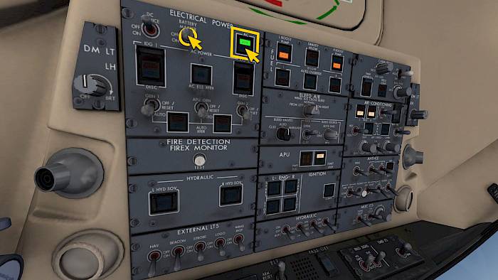
IPACS

Bombardier CRJ900 Flugtutorial

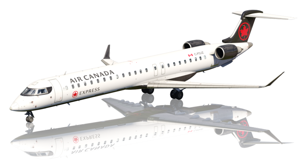
Der Canadair Regional Jet 900, besser bekannt als CRJ900, bietet eine “cold-and-dark” Simulation im Aerofly FS.

Der Begriff “Cold-And-Dark” beschreibt einen Zustand eines Flugzeugs, das längere Zeit geparkt war und nun für den ersten Flug des Tages vorbereitet wird. Die Triebwerke sind aus und alle Systeme abgeschaltet.

Um den “Cold-And-Dark” auszuwählen wähle zunächst das Flugzeug aus dem Flugzeugmenü aus und wähle dann auf der Flugplatzkarte eine Parkposition an. Dann siehst Du rechts Optionen für “Bereit zum Rollen”, “Vor dem Start” und “Cold-And-Dark”. Wähle letztere aus, damit alle System und Triebwerke zu Beginn abgeschaltet sind.

Wir überspringen einige Prozesse in diesem Tutorial und es sollte nicht für die reale Fliegerei genutzt werden.

Preflight and Engine Start

Power On

Turn on the battery and select external power if available

  • Battery Master ON
  • AC Electrical Power ON

Start APU

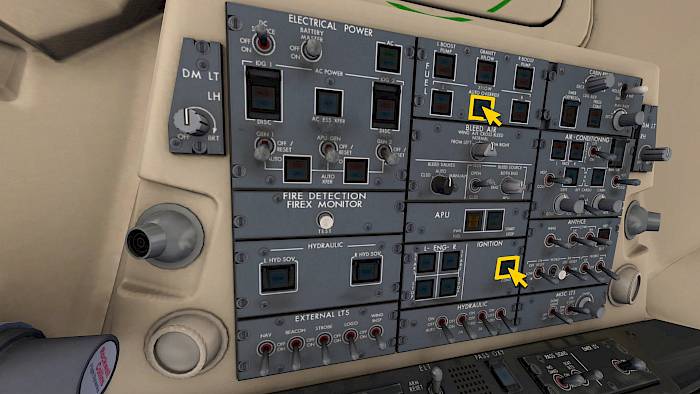
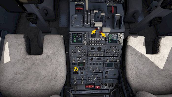
Let’s start the Auxiliary Power Unit (APU) which can provide power on the ground while the engines are not running. We will need compressed bleed air from the APU to start the engines later on.

  • APU PWR FUEL button push once, the APU then performs a self test.
  • Push the APU START/STOP button

IRS, Trim and Yaw-Damper

  • Rotate the two IRS selectors to NAV, the screens will show an ATT ALIGN message until the Inertial Reference System (IRS) has been aligned on the current position
  • Push both STAB TRIM buttons once to turn both stabilizer trim channels on
  • Push the MACH TRIM button to turn it on
  • Push the YD1 and 2 buttons to engage the Yaw Damper

Passenger Signs

On the passenger signs panel (PASS SIGNS)

  • Seat belt signs (SEAT BLTS) on
  • No smoking signs (NO SMKG) on
  • Arm the emergency exit lights (EMER LTS)

Hydraulic Power

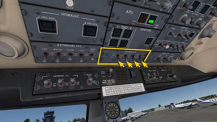
After verifying ground equipment and personell is clear we can power up the hydraulics.

  • Set all four hydraulic switches to the forward position (AUTO/ON)

Select Navigation Source

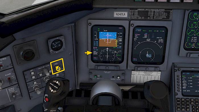
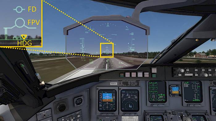
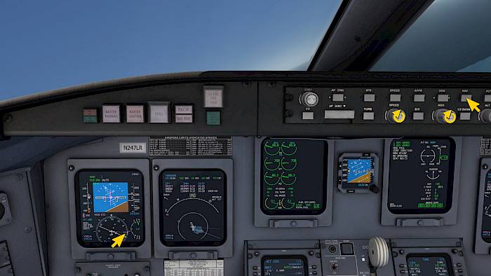
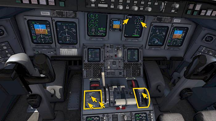
For our departure we want to follow the planned flight plan route. For this we need to select the FMS as navigation source for the autopilot.

  • On the left hand sidewall panel rotate the NAV SOURCE knob to select FMS1 on the PFD

Prepare Autopilot for Departure

Let’s prepare our autopilot for departure. We’ll select runway heading/course, initial altitude and speed.

  • Push the TO/GA buttons on the thrust levers or the FD button on the autopilot panel to engage the Flight Director in TO/TO takeoff modes.
  • Rotate the speed knob to set a target speed of 150KT
  • Rotate the heading knob to match the runway heading
  • Rotate the altitude selector for the initial climb altitude, we’re already setting the cruise altitude here

Engine Start and After Start Checks

Before Start

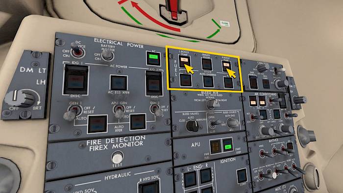
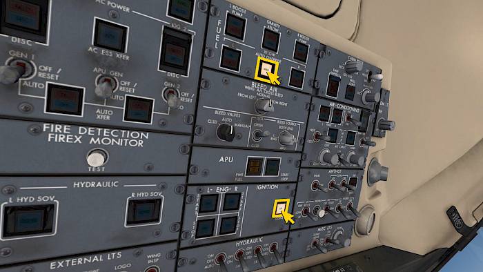
For the engine start we need the APU running to provide pressurized bleed air as well as the fuel boost pumps.

  • Turn on boost pumps with the the L and R BOOST PUMP buttons
  • Set the beacon light on using the BEACON switch in the EXTERNAL LTS panel in the lower left overhead

Engine Start

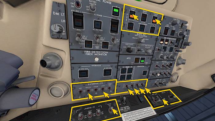
Let’s start the left engine first.

  • Push the L ENG START button. The engine starts rotating.
  • Move the left thrust lever forward from cut-off to the idle position

The engine controller now turns on the ignitors and introduces fuel and starts the engine fully automatically for us. Monitor the interstage turbine temperature (ITT) for a hot start and N2 for a hung start.

Once the engine has stabilized at N2 around 60% we can start the second engine in the same way with the R ENG START button.

APU Off, Packs On

Now that the engines are started we no longer need the APU.

  • Push the APU START/STOP button to shut down the APU
  • After a few seconds you can turn off the APU power with the APU PWR FUEL button

Let’s turn on the Pneumatic Air Conditioning Kits (PACKs) to cool the cabin.

  • Push the L and R PACK buttons, the OFF lights should turn extinguish
  • Set the RECIRC FAN switch next to the buttons to ON

Takeoff Flaps and Trim

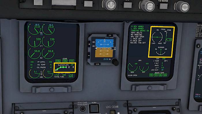
Depending on the takeoff runway length we can use either flaps 8 or flaps 20 for takeoff. On a long runway you can use flap 8 for a better climb performance. In our case the runway is short and we’re using flaps 20 for takeoff.

  • Set the flaps for takeoff with the flap lever next to the thrust levers
  • Set the pitch trim to about 3.8 for departure
  • Aileron and rudder trims should be zero

Flight Control Check

In the pedestal, aft of the thrust levers there are several gray push buttons to change the displayed system synoptic on the right hand EICAS screen.

  • Push the F/CTL button (in the second row, first column) to display the Flight Control synoptic
  • Move your elevator, aileron and rudder through the full range to ensure they work correctly
  • Push the STAT button to display the Status page again

Taxi and Takeoff

Before Taxi And Brake Check

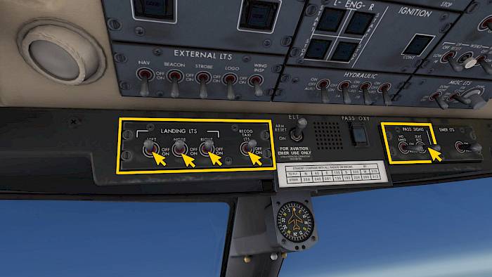
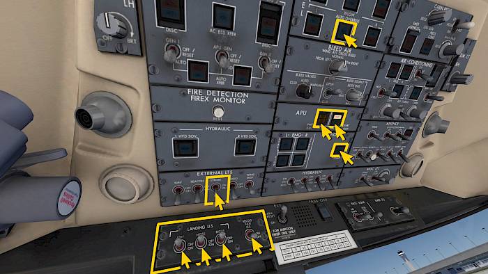
Turn on the necessary external lights.

  • Check that the NAV light is ON
  • Check that the BEACON light is ON
  • Set on the LOGO light
  • Turn on the taxi lights with the RECOG TAXI LTS switch
  • Rotate the ATC transponder selector in the pedestal to ATC1
  • Release the parking brake to start the taxi
  • Test the wheel brakes

Before Takeoff

For redundancy reasons we’re turning on the cross flow override and the continuous ignition.

  • Push the XFLOW AUTO OVERRIDE button in the fuel panel
  • Push the IGNITION CONT button
  • Check that both reverser switches left of the thrust levers are in the ARM position
  • Fold down the Head Up Display (HUD) by clicking on the cylindrical HUD mount

Ready for Departure, Lineup

The left EICAS screen Crew Alerting System (CAS) area should now be blank and on the right hand EICAS screen you should see a green T/O CONFIG OK, L REV ARMED and R REV ARMED text as well as a couple white memo texts.

The T/O CONFIG OK message which indicates that the aircraft is in takeoff configuration and ready for departure.

  • Turn on the STROBE and LANDING LTS switches
  • Taxi onto the runway and line up with the runway centerline

Set Takeoff Thrust

We’re now cleared for takeoff.

  • Set takeoff thrust by placing the thrust levers to the TO/GA detent. This corresponds to full throttle on your assigned joystick.

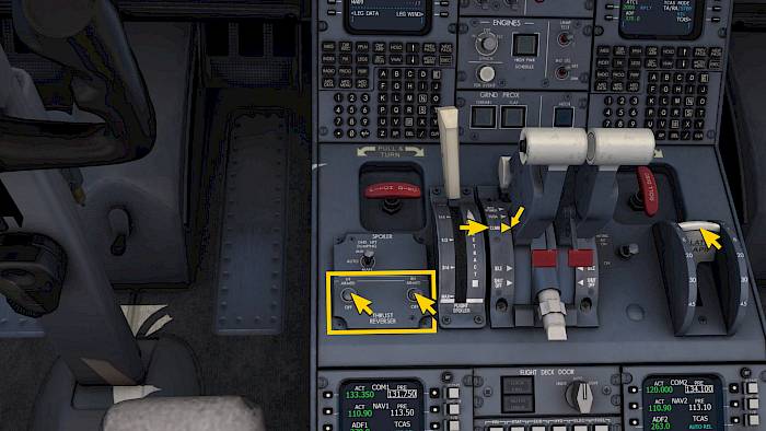
Above the TO/GA detent there is a position for the Automatic Power Reserve (APR) mode which is only used in emergencies. Be careful not to set APR when using your mouse or VR hand controllers.

Takeoff

  • Hold the centerline with rudder inputs
  • At rotation speed, indicated as VR on the airspeed tape on the PFD, gently pull the nose up and lift off
  • Follow the flight director cue (FD) and steer the flight path vector (FPV) onto the flight director circle. On the horizon line you can see your selected runway heading as well as your current heading.

Positive Rate - Gear Up

When you have lifted off and the vertical speed indicator shows a positive rate of climb you can retract the landing gear.

  • Click the landing gear lever to retract the gear

Monitor the gear retraction on your left EICAS screen. When you see three white UP indications the gear is retracted.

Initial Climb

  • Maintain about 150 to 160KT with pitch inputs

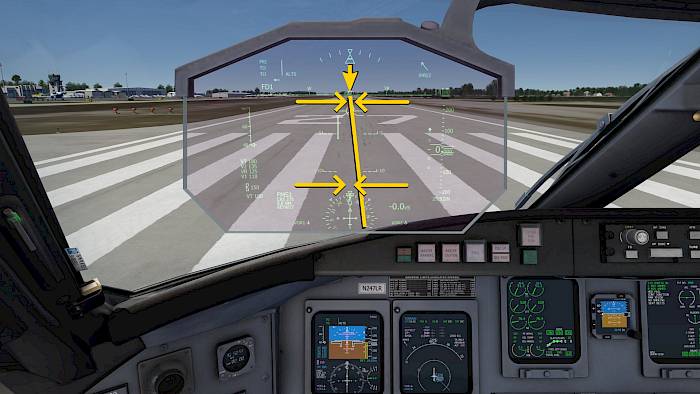
Above 400ft we can turn on the autopilot.

  • Push the HDG button to engage HDG mode
  • Push the SPD button to select CLB mode
  • Rotate the airspeed knob to set 180KT

When you are satisfied with the flight director guidance

  • Engage the autopilot by pushing the AP button

Flaps Up, Set Climb Thrust

  • Select a speed of 210KT to accelerate
  • Move the thrust levers to the CLB position

After passing about 180KT we can retract the flaps

  • Retract flaps with the flap lever
  • Disarm the thrust reversers
  • Increase the selected airspeed to 250KT
  • Change the selected heading to turn on course

After Takeoff

After takeoff we no longer need the continuous ignition and fuel cross flow.

  • Push the XFLOW AUTO OVERRIDE button to extinguish the light
  • Push the IGNITION CONT button to turn off the continuous ignition
  • Turn off the taxi light switch

Climb, Cruise and Descent

Climb

We want to follow the planned navigation route now. For this we selected the navigation source FMS1.

  • Push the NAV button to arm capture of the selected navigation source
  • Rotate the heading knob to turn the aircraft onto an intercept course with the route

Once we intercept the route the aircraft will pick up the route and follows it laterally (LNAV).

  • Climb in CLB mode at 250KT up to 10,000ft.

Cruise

After passing 10,000ft

  • Continue climbing at 280 to 300KT
  • Turn off the landing lights
  • Turn off the passenger seat belt signs if desired

Once the autopilot captures our selected cruise altitude we need to reduce thrust to not overspeed. There is no auto throttle in this aircraft, so we manually have to manage airspeed.

  • Adjust thrust to maintain 280 to 320KT
  • Change the selected airspeed to set your own desired target speed as reference

Before Descent

We can skip ahead in flight with the Aerofly FS time-skip feature if you want to.

When we see the Top Of Descent (TOD) on our navigation map we can start preparing the descent. When we are about 1 minute out from the TOD a vertical profile appears on our PFD and a white snowflake symbol indicates the planned vertical profile of the route.

The CRJ900 cannot fly the VNAV profile by itself. We have to manually adjust the rate of descent and engine thrust to stay on profile.

  • Select a lower altitude for the descent, e.g. destination field elevation +2000ft

Descent

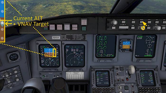
Descent with SPD mode:

  • Push the SPD button to engage the DES mode
  • Rotate the speed knob to set the desired airspeed
  • Reduce thrust to start the descent, to adjust the descent rate and to stay on profile

Descent with V/S mode:

  • Push the V/S button
  • Rotate the vertical wheel to set a vertical speed of -1500 to -2000ft/min to stay on profile
  • Adjust thrust to stay on speed

Passing 10,000ft

  • Turn on seat belt signs and landing lights

Approach and Landing

Auto-Tuning

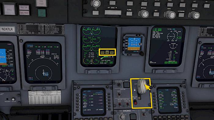
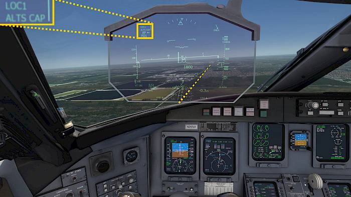
We programmed an ILS approach into the FMS or used the Aerofly FS navigation menu to select an ILS approach which we now want to fly. The aircraft can then automatically tune the ILS frequency and course for us.

The active navigation source is still FMS1 during the descent but now a blue LOC1 appears as preselected navigation source. When we arm the approach and the capture conditions are met the aircraft automatically activates the LOC1 source.

Manual NAV Tuning

You can also manually tune a frequency, set a course, switch the navigation source to LOC1 if you don’t have a flight plan programmed. This is needed if we make quick last minute changes for example.

  • Select HDG mode on the autopilot first
  • Change the navigation source to NAV1 (LOC1/VOR1)
  • Disable the FMS autotuning by setting the FMS tune switch in the pedestal to inhibit
  • Set the ILS frequency
  • Set the ILS course on the HSI

Arm Approach

When you see the FMS source but no blue LOC source within 15NM:

  • Select HDG mode on the autopilot first
  • Switch the navigation source to LOC1

When you are within 15NM and see a valid localizer signal on the HSI

  • Arm the approach mode on the autopilot panel by pressing the APPR button

Approach Capture

The aircraft now automatically performs the NAV-to-NAV transfer if it was armed and activates the ILS navigation source and captures the localizer for us.

After the autopilot captured the LOC signal it can start to capture the glide slope (G/S) as well. We need to monitor our energy with manual thrust inputs and speedbrake to not be too high and too fast when this happens.

Extend Flaps and Gear

  • Reduce speed to 210KT
  • Adjust throttle as needed
  • Extend flaps to 8 when below 230KT

Monitor the glide slope deflection. When the glide slope is one dot above center:

  • Gear down
  • Reduce to 150KT
  • Extend flaps to 20 when below about 170KT
  • Arm both thrust reversers with the L REV and R REV switches in the pedestal

Before Landing Checks

  • At 4 to 5NM out, reduce speed to final approach speed
  • Set full flaps
  • In the overhead panel turn on the XFLOW AUTO OVERRIDE and IGNITION CONT
  • Turn on all external lights
  • Lower the HUD if desired

Landing

Time to get to work.

  • Turn off the autopilot with the autopilot disengage bar or the yoke disengage button
  • Reduce to final approach speed of about 125 to 130KT
  • Adjust thrust inputs and pitch trim as needed

Landing the CRJ900 isn’t much different to other aircraft but depending on speed the height of the cockpit above the runway changes significantly because of the long nose.

Rollout and Vacate

  • Hold the centerline with rudder inputs
  • After touchdown gently lower the nose wheel onto the runway
  • Gently add manual brake inputs (don’t add too much if the nose is not on the ground!)
  • Select reverse thrust
  • Check the EICAS display for REV green on both engines and GND SPLR DEPLOY on the second EICAS display
  • Continue to slow down with manual brakes and stow reversers at 60KT
  • Vacate the runway

Taxi And Parking

Taxi to Terminal

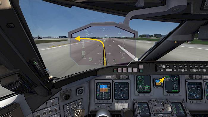
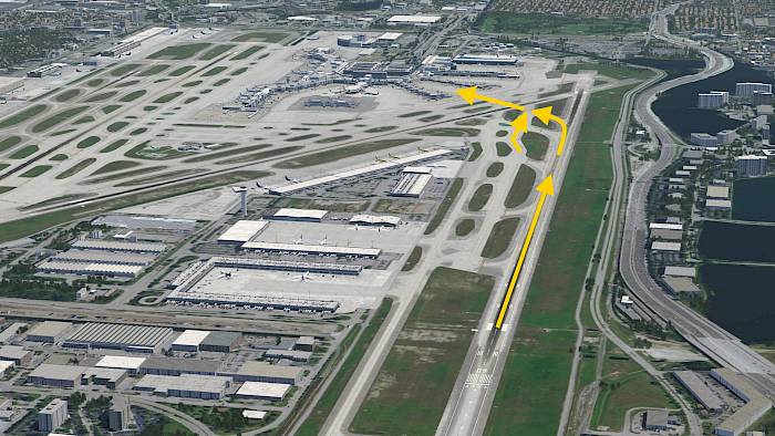
We’ve arrived at Miami in our example flight and vacated the runway with one of the highspeed taxiways. We can now taxi to our parking position at the terminal.

  • Use manual brakes to stay below 25KT ground speed
  • Make sure to hold at the hold short positions when crossing runway

Cleanup After Landing

  • Disarm the thrust reversers
  • Stow the ground spoilers by briefly applying a little bit of thrust or by selecting the GND LIFT DUMPING switch to MAN DISARM and back to AUTO
  • Retract flaps
  • Reset trim for the next takeoff

Lights off, Start APU

  • Turn off the IGNITION CONT and XFLOW AUTO OVERRIDE
  • Turn off the STROBE lights
  • Turn off the landing lights and keep the TAXI lights on
  • Push the APU PWR FUEL button
  • Push the APU START STOP button to start the APU

Engine Shut Down

  • Turn off the taxi lights when turning into the stand

When we have arrived on stand we can turn off the engines.

  • Set the parking brake
  • Ensure the APU is running or establish ground power
  • Click the red levers on the thrust levers to set them to CUT-OFF
  • Rotate the ATC transponder to standby

Parking Checks

Once the engines have spooled down we can turn off the beacon light and release the passengers.

  • Turn off the hydraulics
  • Turn off the L BOOST and R BOOST PUMPs
  • Turn off all external lights, keeping the LOGO light if desired
  • Turn off the PASS SIGNS

Tutorials