
 English
 Deutsch
Dash 8-Q400 Flight Tutorial
In this tutorial we’re flying the Bombardier Dash 8-Q400 from San Diego to Los Angeles.

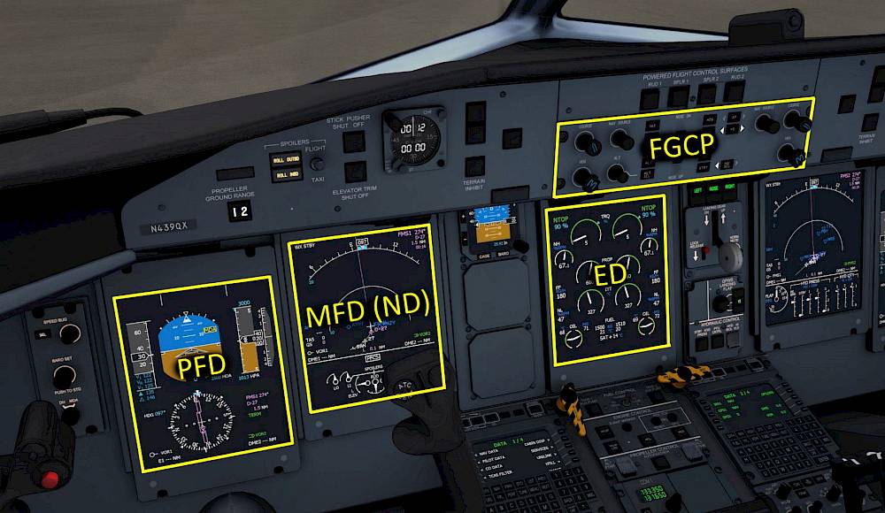
Take your time and look around the Cockpit for a bit. Read the panel names and get an idea where which panel is located. Lets start a bit of a tour through the flight deck of the Q400. Directly in front of the pilot there are two monitors. The left one is the primary flight display (PFD) and the right one is a multi function display (MFD) currently showing the navigation display page (ND) with the flight plan and waypoints on it. The bottom half of the MFD shows the positions of the Primary Flight ControlS (PFCS). In the center of the front panel we find the Engine Warning Display (EWD) that indicates the status of the engines, most interestingly to us: torque (TRQ) percentage and propeller rotation speed (PROP RPM). Directly above the EWD, in the glare-shield, you can find the Flight Guidance Control Panel (FGCP) also called autopilot panel, which we will use to interact with the autopilot.
The PFD displays, left to right, the current airspeed, the attitude, the altitude and the vertical speed. In the lower half of the display you find the horizontal situation indicator (HSI). The primary flight display is the most important display in the entire cockpit. For that reason it is place directly in front of the pilot.

The PFD is split into several parts:

Note - V1 and VR will be removed from the legend as soon as they are passed in the acceleration phase. They come back after touch down when the speed is decreased again. V2 will be removed when it runs of the speed tape and will also come back during the rollout.
The solid triangle represents the flap retraction speed (V FRI). Above this speed you can safely retract your flaps after takeoff.
The triangle outline is the climb speed (V Climb). After the level off (not below 400ft above the field) you can use it as a target when the one engine has failed.

It is quite helpful to set the Minimum Descent Altitude (MDA) marker to 1500ft above the airport elevation. Then we know when to reduce the pitch attitude after the takeoff and start accelerating into the climb phase. Read the current altimeter indication on the right side of the primary flight display (PFD) and add 1500ft, maybe round it up a little bit.
To enter this altitude as MDA

The Electronic Flight Instrument System Control Panel (EFIS Control Panel) can be found forward and left of the throttle quadrant. It has knobs and buttons to control the PFD as well as the MFD (Multi Function Display).
The Multi Function Displays (MFDs) in the Q400 are capable of rendering different pages that a pilot can chose from. The selection of the pages is done with the Engine and System integrated display Control Panel (ESCP) and the adjustment of the navigation display (map) is done with the Electronic Flight Instrument System (EFIS) control panel. For example, you can zoom in on the map, display the localizer deviation or the flight plan, you can visit system pages or display the PFD or ED instead (display swap).


The Engine and System integrated display Control Panel (ESCP) (what a name! I’m not writing that again :-P) is found in the pedestal aft of the throttle quadrant, right behind the TRIM panel.
The knobs in the top left and top right of the ESCP panel are the MFD1 and MFD2 revision selectors which each have 4 options: PFD, NAV, SYS and ENG and control the left and right side MFD mode.
With the selector in PFD the MFD displays the primary flight display, e.g. in case the left screen is broken.
In NAV the navigation display is displayed.
SYS displays a system page. With the push-buttons in the center of the panel the different pages for electrical systems (ELEC SYS), engine systems (ENG SYS), fuel system (FUEL SYS) and doors page (DOORS SYS) can be visited. With the “ALL” button the pages are stepped though, one at a time per click.
With the selector in ENG the engine display is displayed on the MFD in case the center screen is broken for example.

When the MFD revision selector is in the NAV mode (default Aerofly setting for both MFDs) then the navigation display (ND) is shown on the MFD.
The Engine Display shows the most important engine related parameters. It is located in the center of the flight deck to be visible easily by both pilots.

Other parameters displayed are: Oil temperature and pressure, fuel in each wing tank and the fuel temperature, Static Air Temperature (SAT).
The display also displays “REDUCED NP LANDING” at the top (described further down) and the status of the autofeather “A/F SELECT” or “A/F ARM” under specific conditions.
In the overhead panel you can find the controls for most aircraft systems. From top left to bottom right these are:

The “throttle quadrant” in the Q400 moves a lot of levers into one location. Here you can find the parking brake, power levers, propeller speed, flap lever and elevator trim.
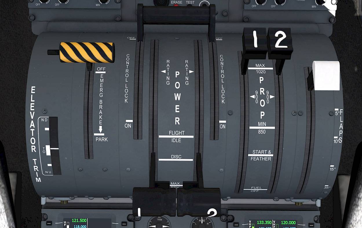
From left to right the quadrant elements are:


There are several derates for the turboprop engines that the pilots of a Q400 can chose from. The selection is made with a movement of the PROP/condition levers and the available push-buttons for engine control in front of the throttle quadrant. The available affect the maximum torque and therefor maximum power of the engines. We modeled all of the Q400 derates which are:

When moving the condition levers the default selections are restored. The default engine derates are mapped to the lever position like this:

After moving the condition levers to the desired rotation speed the default engine derate can be overwritten with the push-buttons on the engine control panel:

To save fuel, engine wear and noise emissions a takeoff with reduced takeoff power can be performed.

To reduce cabin and airport noise during the approach it is common to use a reduced rotation speed of 850 RPM. To be prepared for a go-around with full power available the aircraft is prepared as follows:
Note - To cancel this state either increase power above 50% to perform a go around or push the RDC NP LDG pushbutton a second time.
In the pedestal we find the Audio and Radio Control Display Units (ARCDU 1 and2), the aileron and rudder trim, the Multi Function Display (MFD) control panel and the Weather Radar controls.

The Audio and Radio Control Display Units (ARCDU 1 and ARCDU 2) are the Q400’s interface to the navigation receiver frequencies and audio levels as well as the ATC/TCAS modes and microphone settings.

The ARCDUs have the capability to tune the ILS frequencies of the destination airport fully automatically. They also set the course which is not possible in the real world aircraft. Automatic tuning is only performed when the mode selector of the ARCDU is in “FMS”. The left ARCDU (ARCDU 1) can tune ILS1 and the right ARCDU (ARCDU 2) tunes ILS2 if they are set to “FMS” mode respectively.
The left ARCDU (ARCDU 1) is assigned for the left side frequencies (VHF1, VOR1/ILS1 and ADF1). The right side controls all receivers with the number 2 at the end.
ON - Only editing of the the onside frequencies is allowed
BOTH - The frequencies of the left and right side can be tuned.

Note - When FMS mode is selected or the mode selector isn’t on BOTH and a frequency of the opposite side is selected with the line select buttons then the label will flash. Change the mode to BOTH on each ARCDU device to gain full authority.
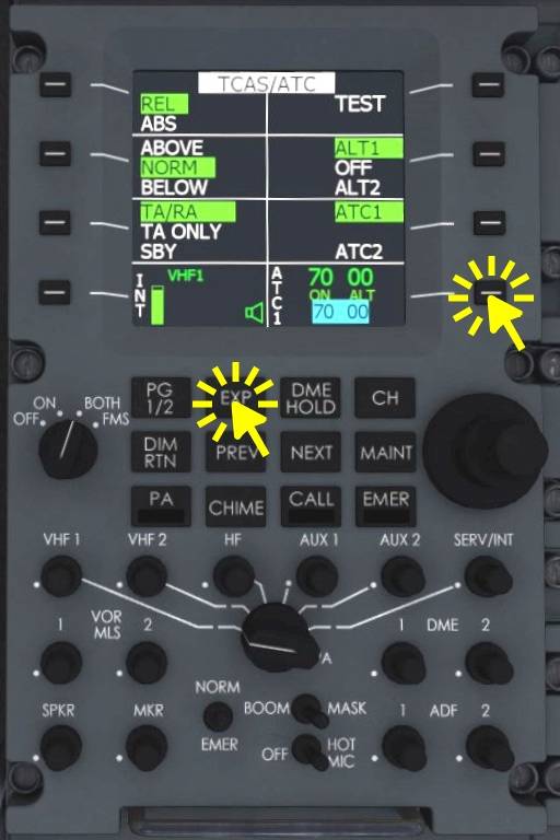
Transponder status
ATC/TCAS details
Note - Similarly you can access expanded pages for VHF1/2, NAV1/2 and ADF1/2. There is also a PG 1/2 button to access page 2 of the ARCDU.

The Flight Guidance Control Panel (FGCP) is the interface to the autopilot and flight director. The left column of push buttons to the left of the vertical wheel in the center are used to change the vertical modes (pitch up and down). The buttons on right column affect the lateral steering mode (bank left or right).
In the center of the panel a vertical scroll wheel can be found that is used to manipulate the selected pitch, selected indicated airspeed or selected vertical speed, which ever mode is currently selected. The direction of the scroll wheel is always in the same manner, scroll the wheel up with the finger and you find the aircraft pitching down, rotating in a similar fashion as the wheel. And if the wheel is scrolled downwards the aircraft follows that rotation and pitches up.
In the lower left and lower right corner of the panel you can find the heading knobs (HDG). These knobs are rotated with the mouse wheel to change the selected heading. Use either heading knob, they are linked together in our simulated aircraft.

Brief explanation of the purpose of each knob:
Whenever a lateral mode is disengaged by pressing the button a second time or when the STBY button is pressed or when the FD is engaging in flight the basic lateral mode engages. When the bank angle at that time is below ~6 degrees the wings are leveled (WING LVL) followed by a heading hold (HDG HOLD) and present heading is maintained. Above that threshold the current bank angle is maintained (ROLL HOLD). Touch Control Steering (TCS) to manipulate this bank angle is not implemented yet.


Unlike most modern airlines the Q400 engineers decided that the altitude capture function should only engage when pilots explicitly press a button to arm it. Since it is very unique for an autopilot we modeled this in the Aerofly FS aircraft but this also means that you have to check if ALT SEL is armed in white on the PFD every time you changed the selected altitude. Typically a press on the ALT SEL push-button is required when you are maintaining the current altitude and want to climb or descent to another altitude. Then another vertical mode has to be engaged and the selected altitude has to be changed and ALT SEL needs to be pushed.
On the upside, if you ever wish to prevent a level off you can disarm the altitude capture (ALT SEL) by holding the ALT SEL button for 1 second.
When ALT SEL is armed in white on the PFD the active vertical mode will change to ALT* (altitude acquire) to capture the altitude followed by ALT to maintain that altitude.

If we don’t do this the autopilot won’t stop climbing automatically.
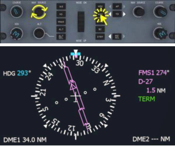
There are four possible navigation sources in total: FMS1, NAV1, NAV2 and FMS2. The selected sources are changed with the NAV SOURCE knobs on the FGCP as well as the HSI SEL button on the same panel.
FMS1 and 2 are the flight management systems of the Q400 that contain the lateral and vertical flight plan.
NAV1 and NAV2 are navigation receivers that can be tuned to a certain frequency to receive VOR or ILS localizer signals as well as Glide Slope (GS) information and distance to the station with their distance measurement equipment (DME). Depending on the frequency NAV1 and NAV2 will be displayed as VOR1 or ILS1 and VOR2 or ILS2.
The selection of a navigation source is done individually on each of the two HSIs (left and right PFD). The flight guidance (autopilot) uses either the left or right side navigation-source as indicated by the HSI SEL arrows on the autopilot panel (FGCP) as well as an arrow on the PFD not in use (pointing to the selected side).

The side where the HSI SEL arrow points is the master. The autopilot will receive the lateral and vertical deviation from that side.
The currently selected navigation source for the HSI is displayed on the PFD, in a small legend next to the HSI. The selected course and course deviation change depending on the navigation-source. The legend is colored in magenta for “FMS” navigation sources and cyan for “NAV” navigation sources. If the pilot and copilot both select the same navigation source the color for the navigation-source will be yellow, e.g. to warn both sides not to change any course or frequency without communicating with the other person.

Note - If LNAV HDG SEL is indicating on the FMA turn the heading knob towards the route to get back on track. LNAV should engage automatically when the route is close enough and can be captured.

To engage IAS hold mode:
Typically, during climb, IAS is used up to a certain altitude before switching back to PITCH HOLD. Three climb profiles can be chosen from:
After that speed is either gradually reduced by about 5kts per 1000ft or the IAS mode is deselected by pressing the IAS push-button again. In the following PITCH HOLD mode the pitch attitude is lowered to about 5 degrees.
During the descent either vertical speed, IAS or VNAV are used. It is also be possible to use PITCH HOLD during some phases in the descent.
For the descent the indicated airspeed mode (IAS) there are multiple descent types:
The vertical flight plan (VNAV) can only be used for the descent planning. The autopilot will fly a fixed geometric path towards the final approach fix and we have to manage the speed ourselves. We can reuse the speed profiles from the IAS descent (see above). Keeping the power lever a bit above FLT IDLE we can, for example, maintain around 240 kts which results in a nice and stable descent all the way into the approach without the need to reduce speed at any point in the descent.

VNAV PATH will engage once the vertical profile is intercepted. To intercept use any other vertical, e.g. vertical speed and either increment the descent rate if you are above profile or reduce sink-rate or even level off when the vertical deviation shows that the flight plan is above you.
When the aircraft’s speed is low (in the red low speed area) or the angle of attack is too high the stick shaker triggers which is audible as a rattling sound.
Reduce the angle of attack by reducing back pressure on the yoke and add power to increase airspeed.
A constant medium pitch beeping sound is set off when you exceed the maximum operating speed of the Q400. This maximum speed changes with the altitude. Look at the PFD speed tape and notice the red overspeed tape.
Gently pull on the yoke to recover from the overspeed and/or reduce the power lever position to FLT IDLE. Check the speed chart on the left side window frame for more the maximum operating speeds under certain conditions and with individual configurations.
When the pitch trim is moving for more than two seconds a constant ticking sound is heard to warn the pilots of a potential pitch trim run away.
If you are manually holding the pitch trim button release the button for a second to stop the warning or just ignore it until you are finished trimming.
On the ground a medium high pitch pulsing warning is triggered when the power levers are advanced for takeoff power and the aircraft configuration is not okay for takeoff.
A constant medium pitch beep sound is heard when the aircraft logic circuits think it should the gear should be down in the current configuration. Often this warning is heard when the power is reduced to idle low to the ground.
Extend the landing gear by either clicking the lever in the cockpit or pressing your button or key assignment (default key: “g”).
A short medium pitch beep is heard when a caution goes off. This is accompanied by a flashing master caution light on the right side of the glare-shield. Click the warning light to stop the flashing and look up to the caution and warning panel (underneath the overhead panel) to read the caution message.
A triple ding is heard when a master warning is triggered. Immediately check the warning panel. When you shut down either engine a few master warnings are to be expected. The usually can be ignored when you are on the ground.
When approaching the selected altitude a high pitch beep sound can be heard. This is just alerting the pilots that the aircraft will level off in about 1000ft and that the pilots should be ready to re-adjust the power, since the Q400 doesn’t have an auto throttle system. When the selected altitude is flown through and the aircraft wasn’t leveled out the sound is triggered again 250ft below or above the selected altitude as to warn pilots they are diverting from the selected altitude.
When flying around for fun or are currently resetting the selected altitude just ignore this warning. When the autopilot is flying make sure that “ALT SEL” is armed in white so that the altitude capture function is activated when you hear this sound. Then adjust the power once the altitude captures.
If you fly on autopilot and hear the warning two times in a row you probably just shot through the selected altitude. Make sure to arm “ALT SEL” next time. For now you have to change the vertical mode to get back to altitude.
When the power levers are retarded below the FLT IDLE detent in flight a loud alternating high-low pitch warning sound is heard (oioioi…). This warning indicates that you should increase your throttle lever until it snaps into the FLT IDLE position. Since the Q400 is equipped with propellers that can pitch flat (DISC 90° to flight direction) and even backwards (REV) to create reverse thrust it is not a good idea to try and pull the power levers aft of the flight idle where they could act as two circular 4.1 m diameter airbrakes.
Keep the power levers above FLT IDLE during the entire flight. Also, during flare, don’t reduce the power to FLT IDLE, keep the power in during the flare to avoid falling from the sky.
