IPACS

Learjet 45 Introduction To The Flightdeck

Overview

Welcome to the flight deck (also called “Cockpit”) of the Learjet 45. The flight deck can be divided into the front panel, pedestal and glare-shield and does not feature an overhead panel.

On the front panel we find several displays which can be reconfigured if needed. From left to right these monitors show the left Primary Flight Display (PFD), the Engine Instrument and Crew Alerting System (EICAS), the two Radio Management Units (RMUs), the Multi Function Display (MFD) and the right PFD.

In the glare-shield two display controllers for the onside PFDs and one Flight Guidance Controller (FGC) are positioned.


Primary Flight Display (PFD)

The Primary Flight Display (PFD) of the Learjet 45 is very similar to airliner PFDs. It features the typical layout with the attitude indicator (ATT) in the center with the flight director (FD), the indicated airspeed (IAS) on the left, altitude (ALT) on the right and a digital radar altitude (RA) at the bottom of the attitude. On the lower half of the display the Horizontal Situation Indicator (HSI) and Vertical Speed Indicator (VS) can be found.

Overview

  • FMA - Flight Mode Annunciator
  • ATT - Attitude Indicator
  • FD - Flight Director
  • RA - Radar altitude
  • IAS - Indicated Air Speed
  • ALT - Altimeter
  • VS - Vertical Speed
  • HSI - Horizontal Situation Indicator

Fight Mode Annunciator (FMA)

The Fight Mode Annunciator (FMA) is located in at the upper edge of the primary flight display (PFD). On the left side it indicates the lateral mode of the flight director (autopilot roll steering) and on the right it displays the vertical mode. In the middle of the FMA the coupling arrow can be found.

  • Lateral Mode - Flight guidance function for roll
  • Vertical Mode - Steering mode for pitch
  • Coupling Arrow - Points towards the PFD that is relevant to the autopilot.

PFD Bezel Controller

Minimums

On the display frame of the Primary Flight Display (PFD) two pushbuttons two rotary knobs can be found. These are used to set minimums and pressure setting.

  • Click the RA/BARO pushbutton multiple times to switch between the modes RA, BARO or none. In the lower right corner of the attitude indicator the selected minimum will be displayed.
  • Rotate the knob to increase or decrease the selected value.

Barometric Pressure Reference

The barometric reference for the altimeter can be adjusted with the knob and pushbutton on the lower right of the PFD frame.

  • Rotate the knob to increase or decrease the selected pressure value. The exact value is displayed below the altitude tape on the PFD.
  • Click the “STD” button to insert the standard pressure value of 1013 hPa or 29.92 inHg. Pressing the button a second time doesn’t change the setting back. Use the knob for this.

Display Controller

The Display Controller can be found in the glare shield of the Learjet 45. It controls mainly the Primary Flight Display (PFD). Click each button multiple times to experiment with its associated function.

  • In/hPa - Changes the altitmeter unit on the PFD from Inches of mercury (inHg) to Hekto Pascals (hPa) and back.
  • CUE - Toggles the flight director style from a single cue to a cross bar flight director
  • FPA - Adds or removes the Flight Path Angle (FPA) from the attitude indicator.
  • WX - Selects or deselects the drawind of the weather radar.
  • HSI - Selected between the 360° rose or 90° arc mode of the HSI. With the navigation source on FMS1 or FMS2 a 90° arc mode with a map for the flight plan is available as well.
  • FMS - On first click activates the FMS1 as navigation source. Following clicks alternate between FMS2 and FMS1.
  • NAV - On first click the NAV1 source (VOR1 or ILS1 depending on tuned frequency) is selected. Following clicks alternate between NAV2 (VOR2 or ILS2) and NAV1.

Customization

Here are two example screenshots to visualize the effects of these customization options:

  • Single Cue Flight Director on the left and Dual Cue FD on the right
  • Rose HSI mode on the left, ARC on the right
  • Bearing 1 with NAV1 needle on the left and OFF on the right
  • Flight Path Vector (Flight Path Angle FPA) visible on the right, parked in yellow on the horizon line

HSI Navigation Source

In total the flight guidance (autopilot) can use one of four different navigation sources: Flight Management System (FMS) FMS1 or 2 or Navigation receiver NAV1 or NAV2. Depending on the frequency the receivers are tuned to the PFD will display “VOR1”/“ILS1” or “VOR2”/“ILS2”.

Here are two screenshots with the FMS1 as source on the left and VOR1 as source on the right screenshot. The currently selected source is always displayed in a legend left of the HSI. FMS sources are usually white and VOR/ILS sources are green unless the copilot and pilot PFD have the exact same source selected. When both sources are the same they are painted in yellow to warn pilots that they have a system of reduced redundancy and that they when they change the navigation course for example that it directly impacts the other side as well.

Selected PFD - Coupling Arrow

If the arrow points away from the onside PFD it means that the navigation source on the other side is used. If we are looking at the left side PFD and the arrow points to the left that means our navigation source is used by the autopilot. If it would be pointing to the right it shows that the copilots PFD would be used instead.

  • Click the XFR button on the Flight Guidance Controller (FGC) to select the left or right PFD as source for the flight guidance/autopilot. The selected navigation source displayed on the HSI is then active.

FMS Navigation Source - “LNAV”

Both navigation sources, Flight Management System 1 and 2 (FMS1, FMS2) provide a lateral offset and a target track which is displayed on the Horizontal Situation Indicator (HSI) when the FMS is the navigation source. The flight guidance uses these to steer the aircraft towards the route.

  • A flight plan has to be loaded, use the navigation menu or CDU inside the cockpit, as described later.
  • Click the FMS push button on the Display Controller to select FMS1 or 2. Preferably the left PFD uses FMS1 and the right PFD FMS2 for redundancy.
  • Make sure the XFR arrow is pointing to your PFD.
  • Click the “NAV” button on the Flight Guidance Controller (FGC) to arm lateral navigation from the Flight Management System (FMS). In other aircraft this would be called “LNAV”, in the Learjet it’s just called “FMS”. A white FMS should appear in the left side of the Flight Mode Annunciator (FMA).
  • Once the route is intercepted the FMS mode activates and the autopilot follows the flight plan.

You can also press the “APR” button to arm the FMS and VNAV approach mode if you have an RNAV approach set up in your route.

VOR/ILS Navigation Source

The Learjet 45 is capable of flying towards the selected course along a VOR radial. The flight guidance uses the selected course, the needle deflection and distance (if available) to capture and maintain the VOR.

  • Tune in the VOR frequency with the Radio Management Unit (RMU). We’ll describe this process later.
  • Click the NAV pushbutton on the Display Controller once or twice to select the correct navigation receiver that you want to use (NAV1 is shown as VOR1 or ILS1 and NAV2 is shown as VOR2 or ILS2).
  • Rotate the CRS knob on your side to change the desired inboard course.
  • Make sure the XFR arrow is pointing to your PFD.
  • Click the “NAV” pushbutton on the Flight Guidance Controller (FGC) to arm VOR capture. A white VOR should appear in the left side of the Flight Mode Annunciator (FMA).
  • Once the needle moves towards the center the VOR mode will capture and the flight guidance steers the aircraft along the radial towards the selected course.

The process is identical for ILS sources. But you can also press the “APR” button to arm the LOC and G/S mode together to fly a full ILS down to minimum.


Multi Function Display (MFD)

The Multi-Function Display (MFD) of the Learjet 45 always displays the MAP/PLAN in the upper half of the display, a bezel menu at the very bottom as well as one of the following pages in the lower half.

Overview of System Pages

  • SUMRY - Summary page of the electrics, hydraulics system and flight control trim values
  • ELEC - Electric system
  • HYD - Hydraulic system
  • ECS - Environment Control System (ECS), air conditioning and pressurization
  • FLT - Flight controls, position of trims and flap and spoilers
  • FUEL - Fuel system, fuel levels
  • TCAS - Small map of surrounding traffic as indicated by the Traffic Collision Avoidance System (TCAS)

Map/Plan Mode

The upper half of the display either renders a Map or a Plan view. The map is an arc section of the flight plan and other navigation aids and the plan mode is a North-up 360° compass rose display.

  • Click the MAP/PLAN button in the main menu of the MFD to toggle between the map and plan mode
  • Rotate the M/P RNG labeled knob of the MFD in the lower right corner to adjust the range of the MAP/PLAN view.

Map Data

Optionally the navigation stations, airports and waypoints can be displayed additionally to the flight plan. To select these rendering options go to the main menu of the MFD first (displayed by default) and then

  • Click the MFD menu button to display the MFD submenu
  • Click the NAV/APT labeled bezel button to cycle through navigation stations, airports or a combination of both.
  • Click the DATA button to show/hide waypoints
  • Click RTN to return to the previous menu.

MFD TCAS Display

To display potential intruders on a map the MFD has a dedicated Traffic Collision Avoidance System (TCAS) map area with a separate zoom level than the Map/Plan in the upper half of the display.

To select the TCAS view

  • Click any RTN labeled buttons to return to the main menu, if not already displayed (default position)
  • Click the TCAS bezel button (third bezel button from the right)
  • Click the same button again to hide the TCAS display later

To increase or decrease the range of the TCAS display

  • Click the line select key next to “TCAS DSPY” Range on the Radio Management Unit (RMU)
  • Rotate the small TUNE knob of the RMU

In a similar fashion you can change the TCAS tilt:

  • Click the lower left line select key of the RMU, labeled “TCAS DSPY” ABOVE/NORMAL/BELOW
  • Rotate the TUNE knob of the RMU to select the TCAS tilt.

MFD System Pages

To select a system page exit out of any previous menu by clicking the bezel button labeled “RTN” (return) or deselect TCAS to get to the main menu.

From the main menu

  • Click the SYS button. The system summary page or any other previously selected page will be displayed now
  • Click any of the bezel buttons to select the respective system page
  • After selecting a page, the “RTN” text will be visible above the page name, pressing the button again returns to the main menu.

V-Speeds

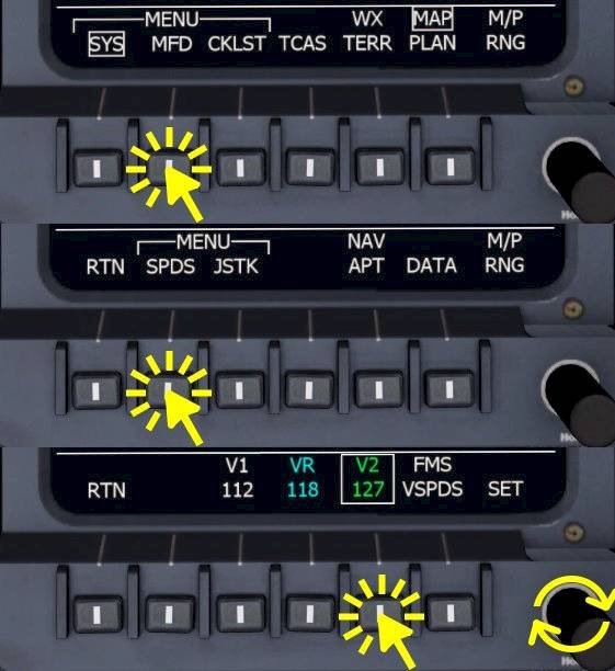
In the Learjet 45 the V-Speeds displayed on the PFDs are set from the MFD menu. To enter the V-Speed menu in the MFD

  • Go to the MFD main menu by following pressing the “RTN” labeled buttons or deselecting TCAS from the main menu
  • Click the MFD labeled button
  • Click the SPDS labeled bezel button
  • Click the V-Speed that you want to edit
  • Rotate the lower right knob of the MFD to increase or decrease the selected v-speed.
  • Press the lower left “RTN” button twice to return to the main menu

Radio Management Unit (RMU)

In the center of the front panel of the Learjet 45 we can find two Radio Management Units (RMUs) that allow manipulation of the communication and radio navigation receivers of the aircraft. In general the RMU is used in the following way: line select the standby frequency, use the adjustment knobs to step the standby frequency then swap the frequencies to activate the set standby frequency.

COM 1/2

The Learjet 45 has two radio communication (COM) transceiver (transmitter and receiver): COM1 and COM2. To change the frequency of the COM1 transceiver:

  • Click the line select key next to the COM1 standby frequency if the device cursor isn’t at the COM1 position anyway
  • Rotate the adjustment fine and coarse knob to adjust the standby frequency
  • Click the upper line select key, next to the COM1 active frequency, to transfer the standby frequency into the active field

NAV 1/2

The RMUs in the Learjet 45 provide the necessary access to the navigation receivers to change the frequencies for VOR or ILS reception. The Learjet has no auto-tuning ability and the pilots have to set the desired frequency and course manually. Per default the left RMU displays NAV1 and the right RMU displays NAV2 but you could access either receiver from either device with the second page (PGE button).

  • Click the lower line select key next to the navigation receiver 1 or 2 (NAV1, NAV2) frequencies. The display will highlight the standby frequency with a yellow box.
  • Rotate the inner knob to change the decimals of the standby frequency (+/- 0.25 kHz)
  • Rotate the outer knob to use coarse +/- 1.0 MHz step.
  • Click the upper line select key to swap the active and standby frequency.

ADF 1/2

Depending on the Learjet version there may either one or two Automatic Direction Finder (ADF) receivers installed. The Learjet 45 for the Aerofly FS has only one ADF receiver. Both RMUs can change the ADF receiver frequency.

  • Click the line select key next to the ADF frequency field.
  • Rotate the inner or outer knob to adjust the active frequency.

Note - There is no standby frequency field available, only the active ADF frequency.

ATC/TCAS

Similarly to the ADF frequency adjustment the transponder squawk code can be set.

  • Click the line select key next four digit squawk code
  • Use the coarse and fine knob to change the squawk code. The speed of the knob rotation affects different positions in the 4-digit code.

The mode of the TCAS system can be change from STANDBY to Traffic Advisory (TA) and Resolution Advisory.

  • Click the lower line select key next to ATC/TCAS box.
  • Rotate the fine adjustment knob to step through STANDBY, TA and TA/RA

TCAS DSPY and TILT

The Traffic Collision Avoidance System (TCAS) Display area on the Multi Function Display (MFD) of the Learjet 45 (TCAS DSPY) can be adjusted to filter out traffic above or below the planned flight path or in the distance, out of close range.

A computational tilt “ABOVE” only shows traffic at or above the current altitude and similarly the tilt “BELOW” only shows traffic that is at or below you. In the “NORMAL” setting only traffic at similar altitude is shown.

The TCAS tilt (above, normal, below) can be changed as follows:

  • Click the line select key next to the “ABOVE”,“NORMAL” or “BELOW” field in the lower left corner of the display.
  • Rotate the fine adjustment knob to step up (towards above) or down (towards below)

The TCAS range as seen on the MFD TCAS view can be changed with the RMU as well. This allows us to zoom in when there is traffic nearby or to zoom out to get a better picture of the incoming traffic.

  • Click the line select key next to the TCAS DSPY (TCAS Display) Range field.
  • Use the fine adjustment knob to step through the available ranges (6, 12, 20 and 40 NM)

Flight Guidance Controller (FGC)

The Flight Guidance Controller (FGC) is the panel which is used to interact with the autopilot, or generally speaking the flight guidance. It dominates the glare shield and is quite accessible there for the pilots.

Summary Of The Autopilot Functions

FD, AP, XFR, YD

  • FD1 and FD2 - Flight Director clear buttons. If autopilot is off they remove the onside flight director from view. When autopilot is on the flight director button on the side where the couple arrow points to acts as a clear command to remove all active modes and return to basic pitch (PIT) and bank (ROL) hold. When the autopilot is off and no mode has been selected yet the buttons have no function.
  • AP - Autopilot master, can be used to activate or disable the autopilot, button is illuminated when the autopilot is on
  • YD - Master switch for the Yaw Damper, selected off before landing and set on after takeoff.
  • XFR - Switches the PFD from left to right and vice versa.

Lateral Modes (Left Side)

  • The HDG knob is used to change the selected Heading. A digital readout of the currently selected heading can be found on both PFDs top right of the HSI (in magenta).
  • The HDG pushbutton selects the lateral mode “HDG” to steer the aircraft towards to selected heading
  • NAV - Activates lateral steering using the selected navigation source (FMS/VOR).
  • APP - Similar to the NAV button but with higher precision used for FMS or ILS approaches.
  • BNK - Reduces the bank limit of the autopilot to 14° for higher comfort.

CRS 1/2 Knobs

  • Change the course of the onside PFD. Caution: When the navigation source on the PFD is illuminated in yellow a change of the course will affect both PFDs at the same time.

SPD Knob

  • Changes the selected airspeed in IAS vertical mode
  • Changes the selected Mach number in MACH vertical mode
  • Changes the selected vertical speed when in VS vertical mode

Vertical Modes (Right Side)

  • SPD button - Activates speed hold (IAS or MACH climb/descent) and pitches up to reduce speed, nose down to gain speed. Current airspeed or mach number is synchronized at the beginning.
  • FLC button - Flight Level Change (FLC) (1 click) or Flight Level Change Highspeed (FLCH) (2 clicks) fixed speed profiles are used as a reference speed for the autopilot pitch command.
  • VS button - Selects the Vertical Speed (VS) hold mode. Vertical speed is always synchronized when this mode is selected.
  • VNV button - Arms the Vertical Navigation function which uses the vertical flight plan from the FMS. Only works with FMS as navigation source and only for the descent when the selected altitude is below the current altitude.
  • ALT knob - Changes the selected altitude
  • ALT button - Commands an instant level off at the current altitude. Target altitude is the altitude at the time the button is pressed.

Flight Guidance Modes (Autopilot)

Lateral Modes

The following lateral modes are available in the Learjet 45: ROL, HDG, VOR, FMS, LOC and VAPP. By pressing the same button twice the basic ROL mode is restored.

  • ROL - Basic lateral mode to maintain bank angle/roll attitude. Below roughly 6 degrees the wings are leveled and current heading is maintained, above that angle the current bank is maintained.
  • HDG - Turns towards the selected heading value. When the HDG knob is rotated in one direction the aircraft will turn that way even if the turn in the other direction may be quicker.
  • VOR - Flies a VOR radial and uses the navigation receiver lateral offset
  • FMS - Reduces the lateral offset to the flight plan and flies towards the FMS target track
  • LOC - Captures and maintains an ILS localizer.

Vertical Modes

In the Learjet 45 we can chose between these vertical modes: PIT, IAS/MACH, VS, ALT, FLC/FLCH, VNAV, GA and ASEL. By deselecting any vertical mode, e.g. by pressing the associated button again, the basic PIT mode is restored.

  • PIT - Maintains the current pitch attitude. In the real world Touch Control Steering (TCS) could be used to change the attitude with the yoke.
  • IAS/MACH - Pitches up or down to accelerate or descelerate towards the selected airspeed or Mach number value.
  • VS - Maintains the selected Vertical Speed value
  • ALT - Maintains the target altitude which equals the altitude at the time the mode was selected. This mode is not affected by the selected altitude!
  • ASEL - Captures and maintains the selected pressure altitude.
  • FLC and FLCH - Uses a static speed profile for climb or descent. In contrast to the IAS/MACH hold this mode will not descent when the selected altitude is higher or climb if the selected altitude is lower. It only flies towards the selected altitude, never away. FLC is normal Flight Level Change and FLCH is Flight Level Change High Speed in the Learjet.
  • VNV - Vertical Navigation, can be used for the geometric FMS descent profile.
  • GA - Fixed pitch up reference, cannot really be used as a guidance

Tutorials