
 English
 Deutsch
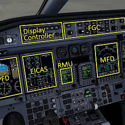
Learjet 45 Flightdeck Introduction
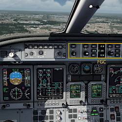
We’re explaining the cockpit instruments, features and functionality of the Learjet 45 in our flightdeck guide.
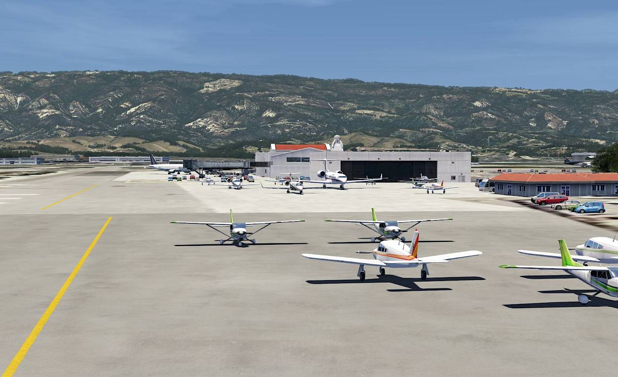
For this tutorial we’re going to do a short flight from the Hollywood Burbank Airport (KBUR), taking off from runway 8. Our route takes us over downtown L.A., over the Hollywood sign, close to the Los Angeles airport, along the coast line to our destination: Santa Barbara Muni (KSBA). We’ll do an ILS approach and land on runway 07. We’ll do a manual sight seeing tour first and then resume the route but you can skip all this if you like. During the flight we’re going to show how to intercept a VOR radial, but you can skip this as well if you like. The parts that can be left out will be marked as optional.
This tutorial should take about 30 to 45 minutes to complete. Before we continue, it is advisable to read the flightdeck introduction.
We’re explaining the cockpit instruments, features and functionality of the Learjet 45 in our flightdeck guide.

In our special tutorial for the UNS-1 FMS you will learn how to enter a flight plan for the 737-500, LJ45 and Q400 in the cockpit.
Learn how to use the powerful route planner of Aerofly FS to create a realistic flight plan.
The checklists used in this tutorial can be found on this dedicated page.
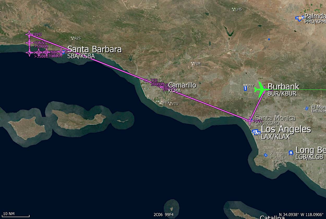
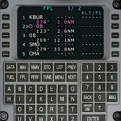
KBUR RWY08 SMO CMA GVO RWY07 KSBA
Create the flight plan as follows, either with the Aerofly FS Navigation Menu or using the UNS-1 FMS.
We’re starting this tutorial “ready for taxi” at the western end of the KBUR parking area from where we’ll taxi to runway 8. Towards the end of the flight we’ll overfly the field and use manual headings to intercept the ILS. We’re actually not going to flying over the Gaviota VOR (GVO) because it bring us too close to the mountains to the North of Santa Barbara.
You can set the conditions as you like, we’re going to use runways pointing to the East so wind coming from the East would be best. Suggested conditions are:
For those who are interested here are a couple of infos for the current setup of the aircraft:
Prior to the flight we recommend setting up a few key commands that we need during this tutorial flight. Please go to the controls menu for the “autopilot” and assign the following functions to keyboard keys or joystick buttons:

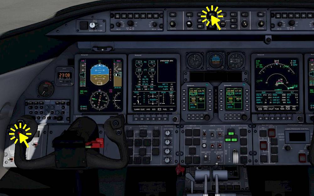
When the aircraft has loaded and you find yourself in the cockpit please set the parking brakes right away so that we have time to prepare and perform a few actions before we start to taxi.
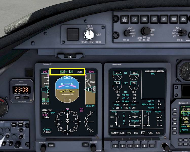
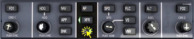
Note - You can also press the “HDG” pushbutton on the Flight Guidance Controller (FGC) to select the heading mode. Then the go around (GA) vertical guidance mode will automatically be selected as well. A second click on that “HDG” button will select the basic “ROL” mode and you should get the same result.

For our own guidance we’re going to put the heading bug to the runway direction, so that we have something to aim at after lift off to fly a straight takeoff.
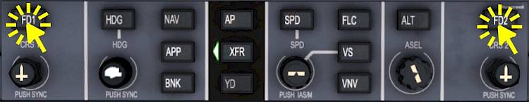
On the Flight Guidance Controller (FGC)
Note - Do not press any other buttons on the FGC at this time, there should be no button illuminated yet, except the XFR arrow. If there is any button illuminated: Click the left “FD1” and the right “FD2” buttons to set both flight directors to off and to clear all flight guidance modes.
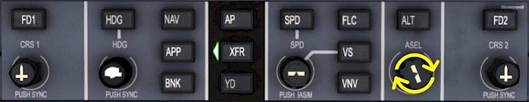
We’re going to dial in the cruise altitude of 18,000ft as our select altitude so that we can climb unrestricted. If you plan to do the little sight seeing tour select 2000ft for now.
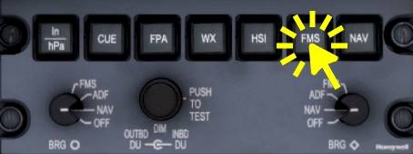
We’re going to set the navigation source to FMS which will allow the autopilot to follow our flight plan and we also get the lateral offset to our flight plan on our PFD. In the air we are going to engage the flight guidance “NAV” mode which uses the selected navigation source to steer the aircraft. With our selected navigation source being “FMS” the NAV mode will give us a lateral navigation from the FMS (LNAV in other aircraft) which we need to fly along the route.
Note - FMS1 should be indicated on the primary flight display, in the legend left of the HSI rose. If FMS2 is now showing that is fine, to set it to FMS1 just press the “FMS” button again.
Let us quickly review the meaning of the three V-speeds: V1, VR and V2
V1 is the takeoff decision speed, also called “V go”. When a critical malfunction occurs like the failure of an engine we can abort the takeoff roll when we are slower than V1. When we are already faster then V1 either the runway is not long enough to stop from that point with that high speed or the maximum brake energy would be exceeded which may also result in an runway overrun. Above V1 we are committed to the flight, we have to continue the takeoff.
VR is the rotation speed at which the yoke is pulled aft to lift the nose off the ground.
V2 is the climb speed for the initial segment after lift off up to flap retraction. This speed is flown when one engine failed during the takeoff and we decided to continue into the air, above V1. Typically the speed actually flown in the first segment is V2 + 10KT or faster.
With our current takeoff mass of roughly 7100 kg or 16,000 lb the v-speeds are:
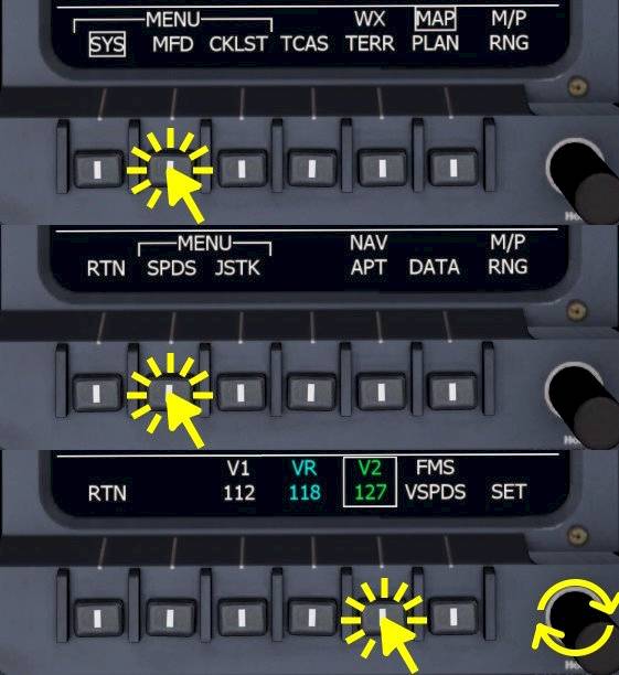
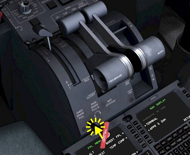
To edit the speeds we’re going into the MFD menu as already shown in the cockpit introduction.
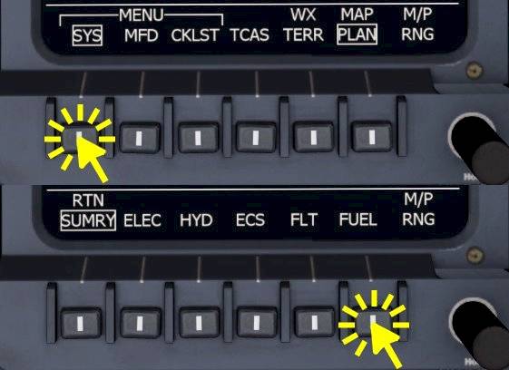
Select FLT page on the left MFD and and SUMRY on the right MFD.
On the EICAS screen you do not have sub-menus, you can quickly select any page by clicking the bezel select button next to the page name.
Before we get rolling we’re going to check the flight controls, move your control inputs to make sure they are working as intended.
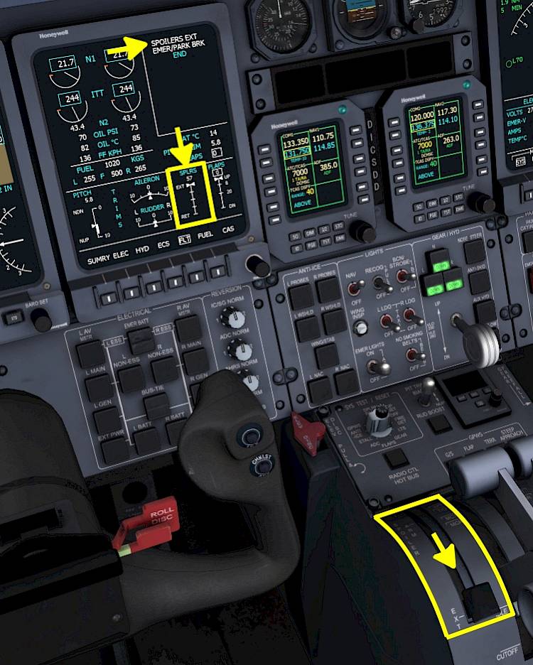
Extend the spoilers and check if they extend symmetrically.
The spoilers extension is visible on the Engine Indication and Crew Alerting System display (EICAS) in the Crew Alerting System (CAS) as text info SPOILERS EXT as well as in the spoiler position indicator.

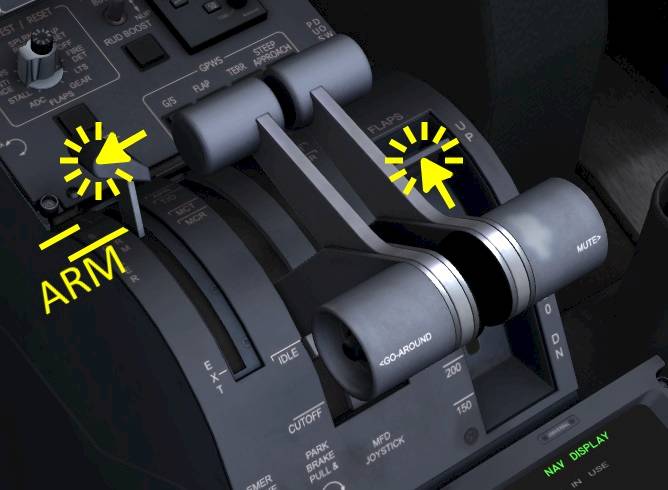
Move the spoiler lever all the way forward and just a tiny bit aft, to about 5% of the lever position where the “ARM” position is labeled. This will arm the automatic spoiler extension in case of a rejected takeoff. The Crew Alerting System (CAS) will show AUTOSPLR ARMED in white.
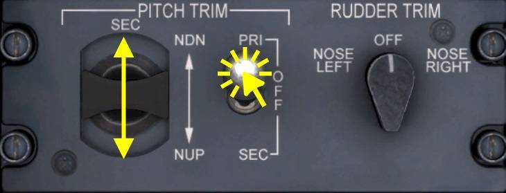
Our center of gravity is about 20% MAC, that means we’re going to use about 5.9 units of pitch trim. This should already be set and no action should be required.
To manually adjust the pitch trim setting we can either
To use the secondary pitch trim switch in the pedestal
| Takeoff Pitch Trim | |||||||
|---|---|---|---|---|---|---|---|
| CG %MAC | 1 - 10 | 12 | 14 | 16 | 18 | 20 | >22 |
| Trim Setting | 8.7 | 8.1 | 7.6 | 6.4 | 6.4 | 5.9 | 5.3 |
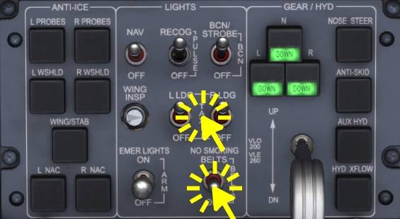
Configure the external lights as described below, a lot of this should already be set by default, just make sure they are set correctly.
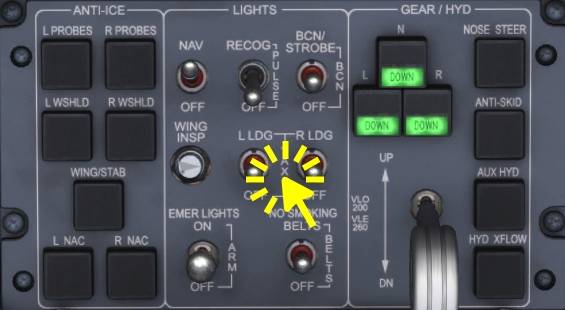
On the LIGHTS panel
| Before Taxi Checklist | |||||
|---|---|---|---|---|---|
| No. | Location | Panel Name | Action | Remarks | |
| 1 | Controls | Flight Control | Free and correct | CHECKED | Test your assigned controls |
| 2 | Quadrant | Spoiler Lever | Autospoilers | ARMED | |
| 3 | Lower Front Panel | LIGHTS | NO SMOKING BELTS | ON | |
| 4 | Lower Front Panel | LIGHTS | TAXI LIGHTS | ON | |
| 5 | Lower Front Panel | GEAR/HYD | NOSE STEER | ON | Should already be on, button pressed in |
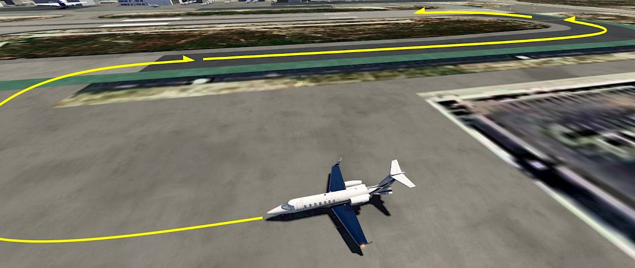
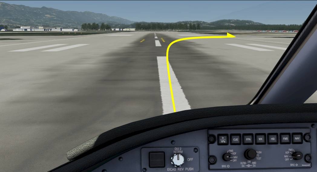
We’re going to taxi out to Runway 8 which is already parallel to our parking position, off to our right. Turn right onto the taxiway and follow it onto the runway 8.
We’re ready to taxi and can now release the parking brake to get going.
To start taxiing, release the parking brake
| Taxi Checklist | |||||
|---|---|---|---|---|---|
| No. | Location | Panel Name | Action | Remarks | |
| 1 | Controls | - | Brakes | TESTED | |
| 2 | Controls | - | Reverse | TESTED and STOWED | |
| 3 | Front Panel | PFD | V-SPEEDS | REVIEWED | |
| 4 | Front Panel | EICAS | TRIM | SET 3x | Pitch 5.9 units, Rudder and Aileron 0.0 |
| 5 | Front Panel | EICAS | FLAPS | INDICATION CHECKED | Flap display should display takeoff flap setting, 8° |
| 6 | Lower Front Panel | PAX OXYGEN | HI FLOW | OFF | |
| 7 | Lower Front Panel | PAX OXYGEN | L/R BLEED | AS REQUIRED | |
We’re now cleared for takeoff and are rolling onto the runway and will do our spool up shortly. Before we takeoff there are a few items remaining that we need to do now before we can start the takeoff roll.
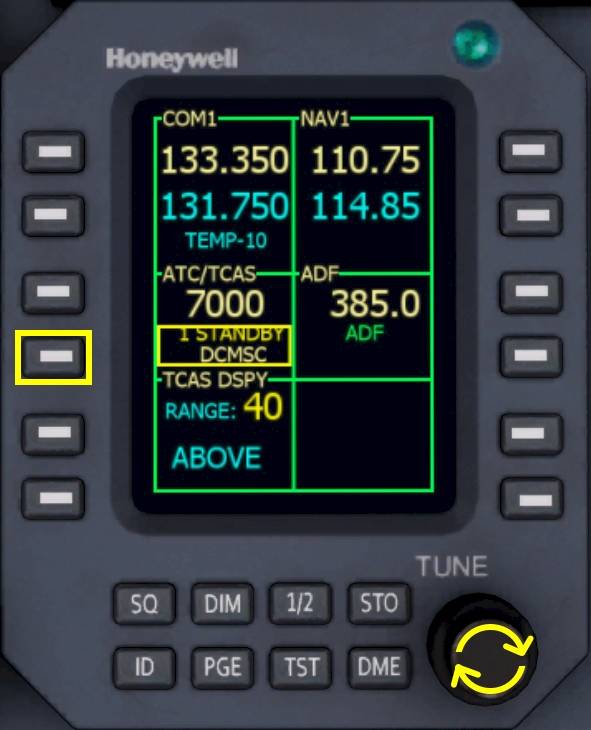
Let’s turn on the transponder using the RMU

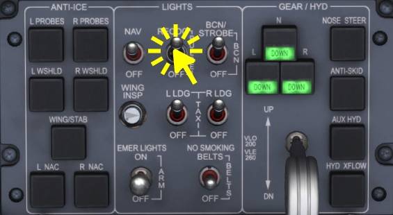
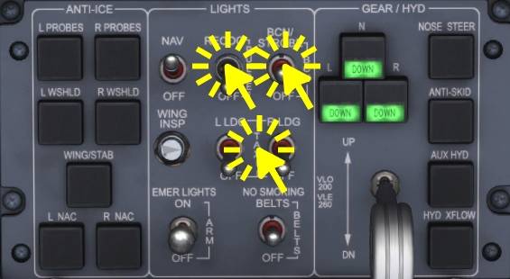
We are rolling onto an active runway and will therefor turn on our strobe light and also set the landing lights to on since we already have the takeoff clearance. Some Learjets also have recognition lights, we’re going to set them on as well.
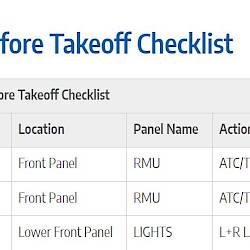
| Before Takeoff Checklist | |||||
|---|---|---|---|---|---|
| No. | Location | Panel Name | Action | Remarks | |
| 1 | Front Panel | RMU | ATC/TCAS MODE | TA/RA | |
| 2 | Front Panel | RMU | ATC/TCAS TILT | ABOVE | |
| 3 | Lower Front Panel | LIGHTS | L+R LANDING LT | ON | |
| 4 | Lower Front Panel | LIGHTS | BCN/STROBE | STROBE | |
| 5 | Front Panel | EICAS | PAGE | FLT or SUMRY | |
| 6 | Front Panel | MFD | PAGE | SUMRY or FLT | Different from EICAS |
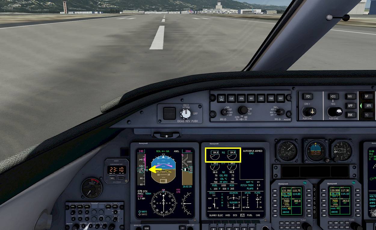
Hold the brakes. Advance your throttle control input forward until you see an N1 indication of 85 to 86% on the EICAS (first round two dials from the top). We call that takeoff thrust set, release your brakes.
The aircraft will accelerate quickly, maintain the center line of the runway with rudder and gently pull back when the speed exceeds VR of 107KT. Rotate with about 3 to 5 degrees per second.
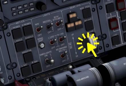
When airborne retract the landing gear.
or roughly where the selected airspeed bug is placed, 140KT. Ignore the flight director pitch guidance, it only indicates a fix pitch angle in the GA mode and is not meant as guidance.

Even if you do not intent to use the autopilot at least press the YD button to improve yaw damping. The Yaw Damper (YD) always comes on when the autopilot is engaged and is disconnected when the autopilot disengages. But you can use the YD any time during flight, just not for takeoff and landing.
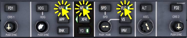
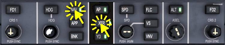
When above 500ft, with stabilized pitch attitude and stable speed, set the autopilot to on. Engage NAV mode now.
Note - When you chose the sight seeing tour and selected 2000ft the autopilot will level off shortly, no need or time to set FLC. Reduce thrust to keep around 180KT.
As denoted earlier this part is purely optional and you can skip all the way to the “After Takeoff” section of this tutorial. If you do want to do this maintain a speed of 180KT for this right hand turn to work as intended with the autopilot or just fly manually.
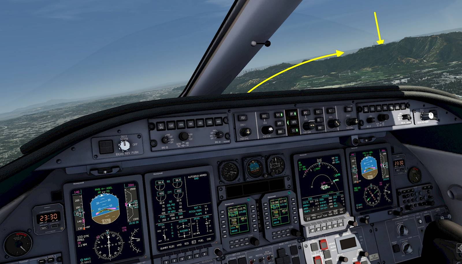
Plan is to swing around the hills off to our right. On the back side, facing L.A. there is the Hollywood Sign tourist attraction which our passengers want to see. There is also a little tower up on that hill which you should be able to see after the first right turn of the flight plan.
We’re going to use heading select to steer around that mountain and we’re only using half bank angle so that we can see the sign from the cockpit as well, even from our left seat if everything goes as planned. :) You can of course fly this part manually if you like, fly around the hill a couple of times.
This isn’t totally realistic, you probably can’t fly that close to the sign in real life, but hey, we’re having fun and pretend to have rich people in the back who will pay for all fines, right?
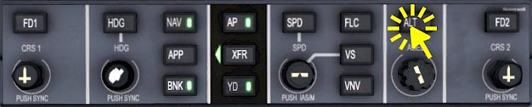
Because we set the selected altitude to only 2000ft earlier the autopilot has already leveled off now. Another way to level off any time a.s.a.p. would be to press the “ALT” button on the FGC. The altitude at the time of the button press is stored as target altitude and the autopilot is going to maintain that altitude.

Now select heading 120° and fly a speed of 180KT.

Watch the HSI on your PFD. When it flips right to the next waypoint and no longer points towards 123° wait 10 seconds, then rotate the selected heading right to 210°, still with reduced bank limit.
When you are confident you can turn further right at your discretion.
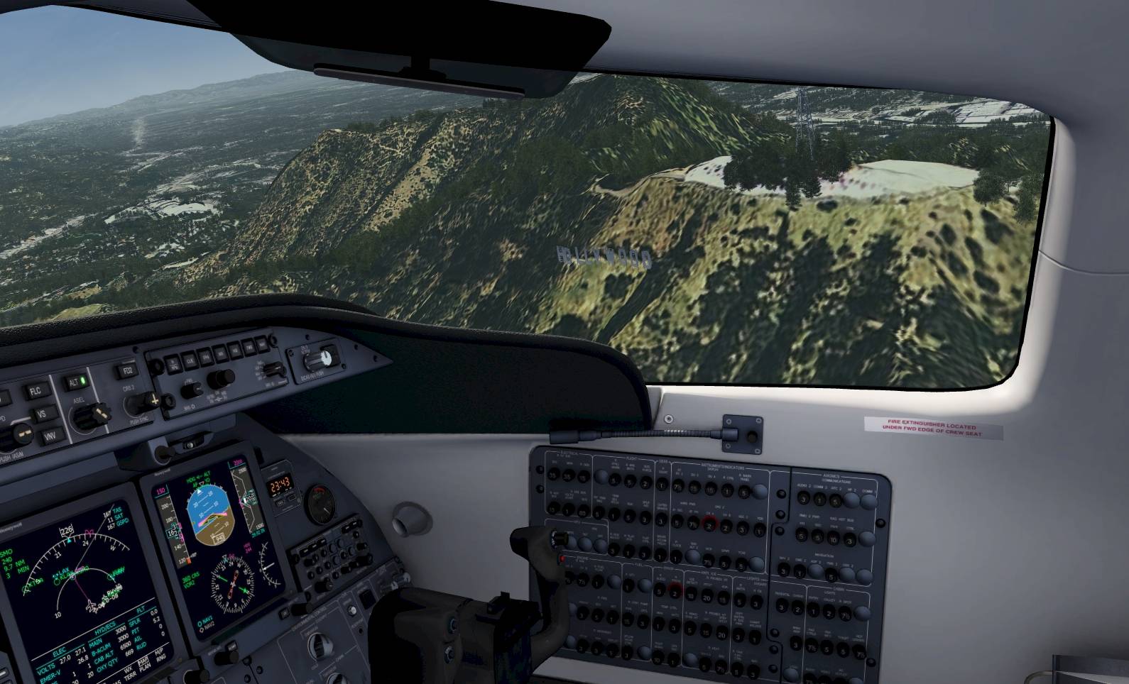
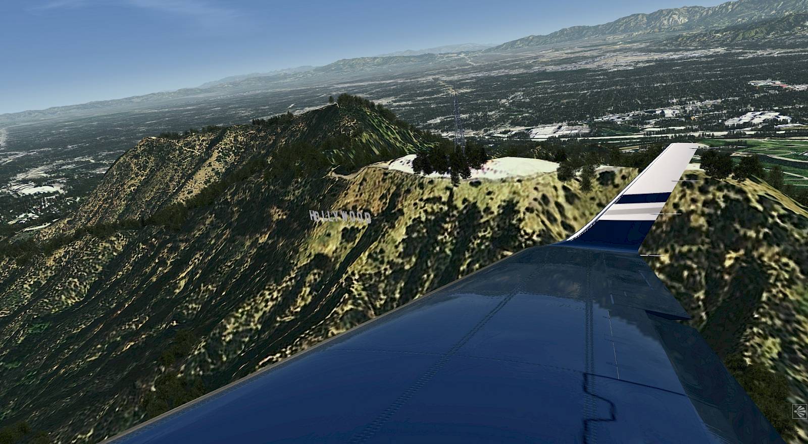
It should look something like this, when you are close to the sign.

Look at the PFD and depending on the position of the deviation bar adjust the selected heading left or right to reintercept the leg. Click the NAV button on the FGC as shown earlier. The autopilot will pick up the flight plan in FMS mode shortly.

When we accelerated above V2 + 25KT (141KT today) we can select flaps up. And while we’re at it, disarm spoilers.
Even if you do not intent to use the autopilot at least press the YD button to improve yaw damping. The Yaw Damper (YD) always comes on when the autopilot is engaged and is disconnected when the autopilot disengages. But you can use the YD any time during flight, just not for takeoff and landing.
| After Takeoff Checklist | |||||
|---|---|---|---|---|---|
| No. | Location | Panel Name | Action | Remarks | |
| 1 | Lower Front Panel | GEAR | GEAR POSITION | RETRACTED | |
| 2 | Front Panel | EICAS | FLAP POSITION | RETRACTED | |
| 3 | Front Panel | EICAS/SPOILERS | AUTO SPOILERS | RETRACTED | |
| 4 | Glareshield | FGC | YAW DAMPER | ON | |
At 10,000 feet altitude we can switch off the landing lights and release our passengers.

After passing 18,000ft altitude
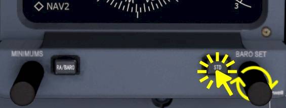
Reaching 18,000ft (transition altitude in the U.S.) we are going to set all three altimeters to the ISA standard pressure of 29.92 inHg or 1013 hPa.
Note - The pressure indication won’t switch to a text “STD”, it just sets the pressure value to the standard pressure. To switch back to local pressure just turn the BARO SET knob right next to the STD push button on the PFD bezel selector.
| Climb Checklist | |||||
|---|---|---|---|---|---|
| No. | Location | Panel Name | Action | Remarks | |
| 1 | Lower Front Panel | LIGHTS | LDG/TAXI | OFF | Above 10k |
| 2 | Lower Front Panel | LIGHTS | BELTS | AS REQUIRED | Above 10k |
| 3 | Front Panel | PFDs, Standby ALT | ALTIMETER | STD 3x | Above 18k |
| 4 | Lower Front Panel | LIGHTS | RECOGNITION LIGHTS | OFF | Above 18k |
Remember that this aircraft does not have an auto throttle system and we have to manage speed ourselves. When the autopilot starts to level off at the desired altitude reduce the thrust to maintain a speed of about 280 knots, we used about 72% of N1 in our testing.
This is another optional part where we’re going to intercept a VOR radial with the autopilot of the Learjet 45. Skip this section as desired.
The plan for this section is to get a better understanding of the navigation source selection and the coupling arrows and XFR switch. We’re going to interact with the RMUs, use the copilot PFD to intercept the signal from nav source 2 and then resume the flight over Camarillo in FMS mode, before we need to start the descent.
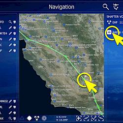
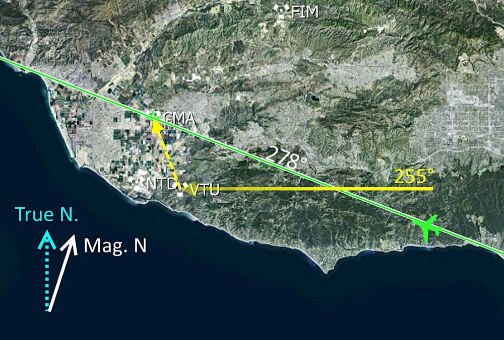
We are at cruise altitude with a heading of about 278° or still during the climb, just after Santa Monica VOR (SMO) and well before the Camarillo VOR (CMA) station. We’re going to intercept the 255° radial towards Ventura VOR (VTU) and then turn back onto the flight plan, for this we will prepare everything on the right PFD and then just switch the navigation source from left to right PFD with the XFR switch.

NAV2 should already be source on the right hand PFD but if it isn’t:
Use the right display controller:

The frequency for the Ventura VOR is 108.20 MHz. To tune in this frequency:
When the frequency of 108.20 is set in the cyan standby field transfer it across to the active field:
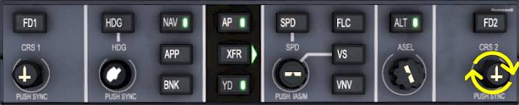
The inbound course that we want to use is 255° but you can decrease that further if the course deviation indicator on the HSI is already left of the aircraft symbol. In that case use 240 or something like that, it is important that the needle is still right of the HSI center, otherwise we can’t intercept the turn with the present heading.
To adjust the course of the NAV2 use the CRS2 knob (right CRS knob!)
Each PFD has its’ own navigation source, which can be FMS1, FMS2, NAV1 or NAV2. We select which one we want on our PFD with the onside display controller.
The autopilot then uses either the left or the right PFD’s selected navigation source depending on the coupling arrow direction and we can change which one has priority with the XFR button.
This makes it possible to have the FMS on the left side and the NAV2 on the right side, like in our case, and then quickly switch from one source to the next.
Currently the autopilot is still tracking our flight plan FMS mode from the left PFD, time to change that. First we’re going to change which PFD the autopilot is using, this will cause the autopilot to fall out of the FMS mode coming from the left side, back into its basic mode which is ROL. ROL means wings level when the bank angle is less than 6° and bank hold above that. We should be careful switching nav-sources when our current bank angle is high, we have to make sure that we’re not staying in ROL because the autopilot is just going to continue turning, no matter what… A safer option is to use the heading mode.
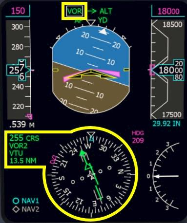
Once the autopilot captures the VOR the FMA will display VOR in green. The screenshot shows the right side PFD when the VOR mode activates.
Let me summarize the actions we did so far:
When the signal is received and the station is identified on the right PFD we can arm the VOR capture mode:
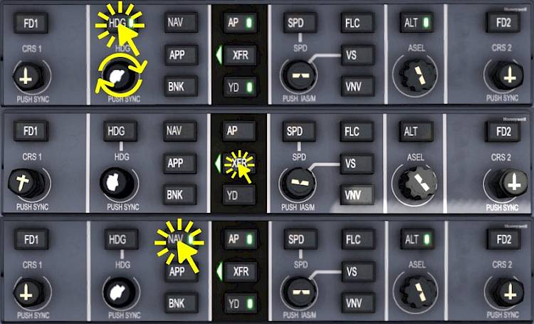
Now that we have demonstrated how to capture a VOR, we’ll rejoin our route. We still have the FMS selected on our left PFD so we can just swap back to the route but we’ll have to re-intercept the route to capture it.
The FMS mode will engage once you are back on the flight plan. You can adjust the intercept HDG by rotating the HDG knob to accelerate this process.
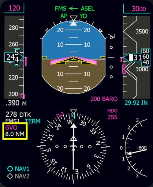
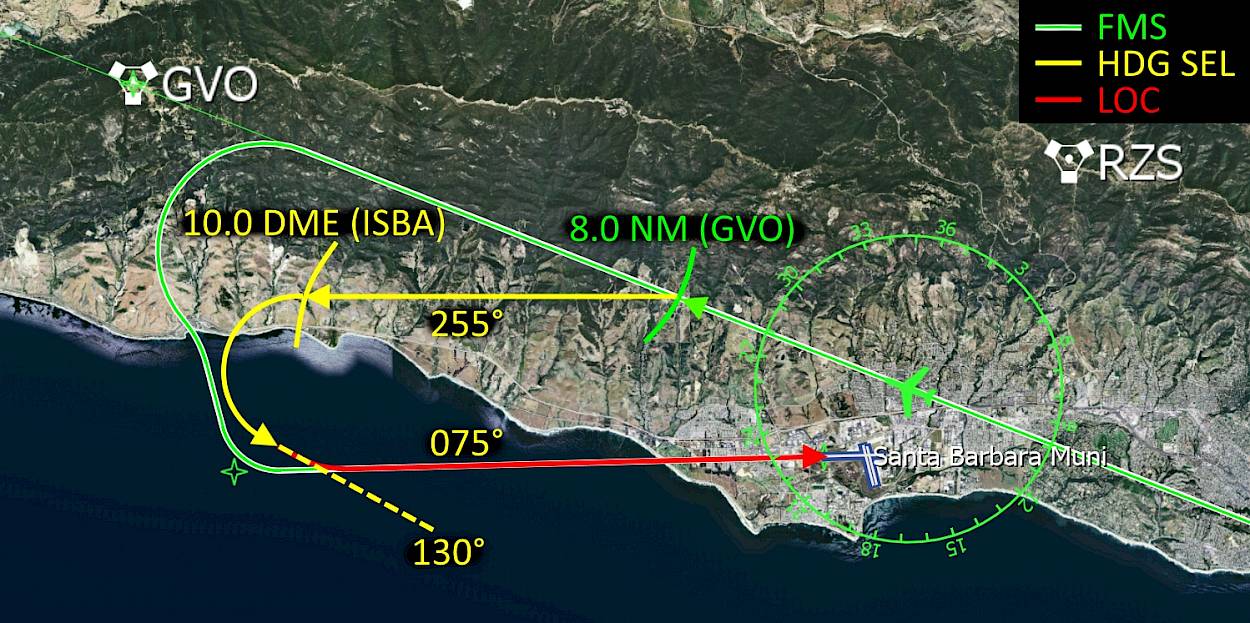
Shortly after Camarillo VOR (CMA) we are going to start our descent down to 3000ft, descending in vertical speed mode (VS) at a rate of -2000ft/min with 250KT indicated airspeed. At 8.0NM DME before the Gaviota VOR (GVO) we are going to break off from the flight plan and turn left to 255° and slow down to 180KT. At 10.0NM DME from ISBA we are going to turn left to 130° and intercept the localizer of runway 07.
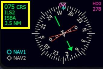
We are going to fly the ILS 07 approach into Santa Barbara Muni (KSBA), the ILS frequency is 110.30MHz, the approach course is 075°. The ILS localizer goes out to the open water of the Pacific Ocean, so no obstructions to worry about once we are established.
The airport elevation of KSBA is 14ft and the runway is 6000ft long (1830m). On rollout we are going to turn right onto the first taxiway after the two intersecting runway.
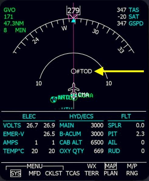
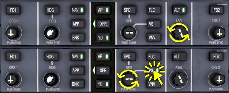
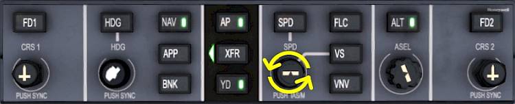
We are going to start our descent at the white #TOD marker on the map. Take a look at the MFD map display to see the position of the top of descent in relation to our aircraft. To start the descent we need to select a lower altitude and then press the vertical speed button on the Flight Guidance Controller (FGC). We’re going to descent to 3000 feet and use a vertical speed of -2000 feet per minute.
We are now below the transition level of 18,000 feet in the U.S. so we have to switch back to the local pressure at the airport.

At 10,000 feet during the descent we are going to set the lights and seat belt signs back on.
| Descent Checklist | |||||
|---|---|---|---|---|---|
| No. | Location | Panel Name | Action | Remarks | |
| 1 | Front Panel | PFDs, Standby ALT | ALTIMETER | STD 3x | Below 18k |
| 2 | Lower Front Panel | LIGHTS | RECOGNITION LIGHTS | ON | Below 18k |
| 3 | Lower Front Panel | LIGHTS | BELTS | ON | |
| 4 | Lower Front Panel | LIGHTS | LDG/TAXI | ON | Below 10k |
| 5 | Front Panel | EICAS/MFD | FUEL IMBALANCE | CHECKED | |
| 6 | Lower Front Panel | PRESSURIZATION | LDG ALT | SET | |
During the descent we are going to prepare the approach into Santa Barbara. We are going to fly in FMS on our flight plan up to 8 NM to Gaviota VOR (GVO) where we are going to turn left to 255° onto the downwind. By then we will have the approach set up fully so that we can switch our navigation source from FMS to NAV on our left PFD. We will slow down to 160KT and set flaps 5°. When we reach a distance of 10 NM to the localizer we will turn left to 130° to intercept it. The autopilot will intercept the localizer for us so that we can run final checks while it does that. At 200ft above the ground we have to disengage the autopilot and land manually.
Note - This arrival route doesn’t exist in the real world, I made this up for Aerofly FS training purposes.

This may look complicated at first but it is actually really simple. All you have to do is look at the PFD, left of the HSI on the distance that is sown. The first time you will just have to press one button when the number is 8.0, the second time you just have to scroll over the heading select knob when the distance reaches 10.0. We will prepare everything in time, there isn’t that much to do and we have a lot of time in between.
We are now going to prepare the ILS on the NAV1 and NAV2 receivers. For this we have to tune the receivers manually, set the navigation source to ILS1 or ILS2 and set the correct approach course.
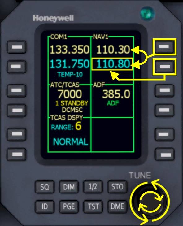
First we are going to set the frequency for the Santa Barbara ILS (ISBA), which is 110.30MHz, on both NAV1 and NAV2 receivers.
On the left Radio Management Unit (RMU)
Repeat for NAV2 on the right RMU, in exactly the same way.
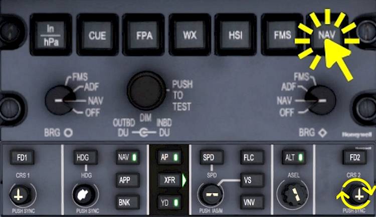
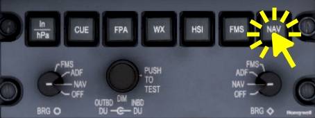
Next we have to set both courses to 075°. We are going to do this on the right side PFD so that we can continue flying in FMS with the flight plan and don’t interrupt the autopilot. First we select the NAV1 navigation source on the right PFD:
Repeat for NAV2: Press the NAV button of the right display controller a second time to select NAV2, then rotate the CRS2 knob again and set the same course as in NAV1.
Later on we are going to switch the left side PFD nav source to NAV1 and leave the source on NAV2 for the right side. Then by a single press on the APP button on the FGC we can arm the ILS approach. But we’re not quite there yet, we have to descent a little bit further and position ourselves for the intercept.

We’re going to assume an arbitrary 200ft for the minimum descent altitude (MDA), the lowest barometric altitude to which we can descent without having the runway in sight. If we don’t see the runway we are now allowed to descent below this MDA and we have to go around and either hope for better weather or fly to an alternate airport, e.g. Camarillo.
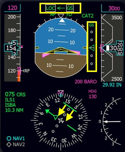
Note - Look at the highlighted area on the screenshot on your PFD, that is where the MDA (“BARO”) value is found.
The approach reference speed (VREF) for our current mass of roughly 15,500lbs and our landing elevation (below 4000ft) is
A typical pattern in the Learjet 45 uses the following speeds:
Note - The Flight Crew Operating Manual (FCOM) states that any use of flaps and spoilers at the same time is prohibited.
→ What does that mean for us?
When we turn onto the downwind leg of our traffic pattern we will slow down to 155KT. We will then extend flaps to 8 degrees and slow down to 145 knots but only after the base turn. When we capture the glide slope we will select the gear down and set flaps 20° and slow down to 135 knots. At around 1500ft we can select the final stage of flaps and slow down to 120KT where the white “RF” is displayed on the PFD.
For our own reference you can adjust the airspeed bug to 120KT. To do so we cannot be in vertical speed mode, so you’ll have to do this a little later, once we have leveled off, or you can press the VS button again to enter PIT (pitch hold) vertical mode for a second, set the speed, then come back to vertical speed mode.
When you are not in VS mode you can adjust the selected speed easily:
| Approach Checklist | |||||
|---|---|---|---|---|---|
| No. | Location | Panel Name | Action | Remarks | |
| 1 | Front Panel | PFD | LANDING DATA | SET | |
| 2 | Front Panel | PFD | MINIMUMS | SET | |
| 3 | Front Panel | n.a. | AVIONICS AND RADIOS | SET | |
| 4 | Lower Front Panel | PRESSURIZATION | HIGH FLOW | OFF | |
| 5 | Pedestal | ENGINE | ENG SYNC | OFF | |
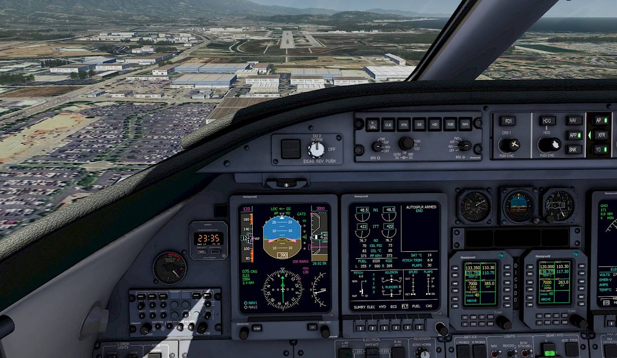
Alright, we have everything set up that takes a bit of time. You should be abeam the airport right now as seen on the approach diagram. Now the fun can begin, we’re going to fly the pattern around KSBA. Continue flying straight for now.
Here is the approach diagram from earlier again:

Slow down to VREF + 40 knots = 155KT but no slower than that.
When the primary flight display (PFD) shows a distance of 8.0 nautical miles (NM) remaining to Gaviota (GVO) (as shown on the screenshot) then activate the heading select mode.
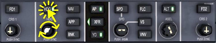
Select the heading for the downwind leg, 255°.
Switch over to the NAV1 navigation source on the left PFD. We already prepared the ILS1 earlier on this navigation source.
The left PFD should now show NAV1, the right one NAV2. Press the individual display controller NAV push buttons a second time if this is not yet case.
We are below the maximum extension speed for flap 8° which are incredible 250 knots in this aircraft. Hence the name LearJET I guess :D
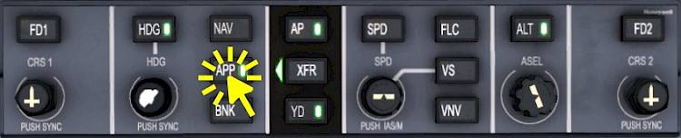
We are about to turn left onto the base leg, we can already arm the localizer and glide slope capture now, or after the turn. To arm the ILS approach mode:
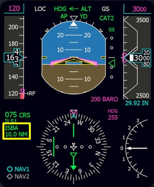
At 10 NM DME from ISBA (as seen on the screenshot) or a bit later (11, 12 or 13 NM should work just as well) turn left to 130° to intercept the localizer. 10 miles is the earliest you can make this turn, that would be the shortest time. But to be sure everything goes as planned count to 10 and then start turning.
Please note - If you are not yet leveled at 3000 feet yet you should also extend further outward until you see the green glide slope triangle between the attitude indicator and altitude tape moving.

The autopilot will directly turn to this new heading because the HDG mode is already engaged.
Note - Make sure you keep your speed at or above 155 knots, adjust your throttles in the turn as needed. When you fly too slow at this point you may end up above the glide slope. You can notice this when that GS remains in white on the first line on the PFD and the aircraft doesn’t seem to descent on it’s own and you can see the runway far below you. In this case just use heading select again, as shown before. Turn back to the left to 255°, speed up to 180 knots, extend the downwind a bit further (beyond 10.0 DME), and then just try again, no big issue!
On the approach diagram we are now flying the 180° turn towards the dashed line.
The Flight Guidance will capture the LOC and very shortly after the glide slope (GS) but only in that order. The glide slope cannot be captured before the localizer even though you may already be established. On the screenshot below I want to raise your attention towards the highlighted areas.
Now that the localizer and glide slope are captured idle the thrust and slow down to VREF + 30KT = 145KT. When you reached 145KT extend flaps to 20° and continue to slow down to 135KT (VREF + 20KT).
At around 2000ft extend the landing gear to help slowing down the aircraft.

Below 145KT set full flaps and decelerate to 120 knots. Adjust the thrust with your throttle levers to maintain that speed.
During landing the ground spoilers will automatically deploy and dump excess lift to increase the wheel friction and improve braking action. The auto spoilers have to be armed for this, like we did before takeoff.
Note - On the EICAS in the Crew Alerting System (CAS) window a “AUTOSPLR ARMED” text will be shown in white.
| Landing Checklist | |||||
|---|---|---|---|---|---|
| No. | Location | Panel Name | Action | Remarks | |
| 1 | Quadrant | SPOILER | AUTO SPOILER | ARMED | |
| 2 | Lower Front Panel | GEAR | AUX HYD | ON | |
| 3 | Lower Front Panel | GEAR | GEAR INDICATION | DOWN 3x green | |
| 4 | Lower Front Panel | LIGHTS | LANDING LIGHTS | ON | |
| 5 | Quadrant | FLAPS | FLAP LEVER | DOWN | Below 150KT, confirm down position on EICAS display |
| 6 | Glareshield | FGC | YAW DAMPER (YD) | OFF | |
| 7 | Front Panel | EICAS/MFD | SYSTEM PAGES | SUMRY and FLT | or vice versa |
The one thing we have to do at the moment is maintain our speed at 120 knots because the autopilot won’t do that for us without auto-throttles. Get ready to take over controls, the autopilot cannot land the plane, we have to.
Disconnect the autopilot before reaching 200ft above ground. The autopilot is only certified for CAT 1 approaches and cannot land automatically.
It is normal that the Yaw Damper (YD) also disengages now. The yaw damper also needs to be disconnect before landing, this is why it automatically disengages whenever the autopilot disengages.
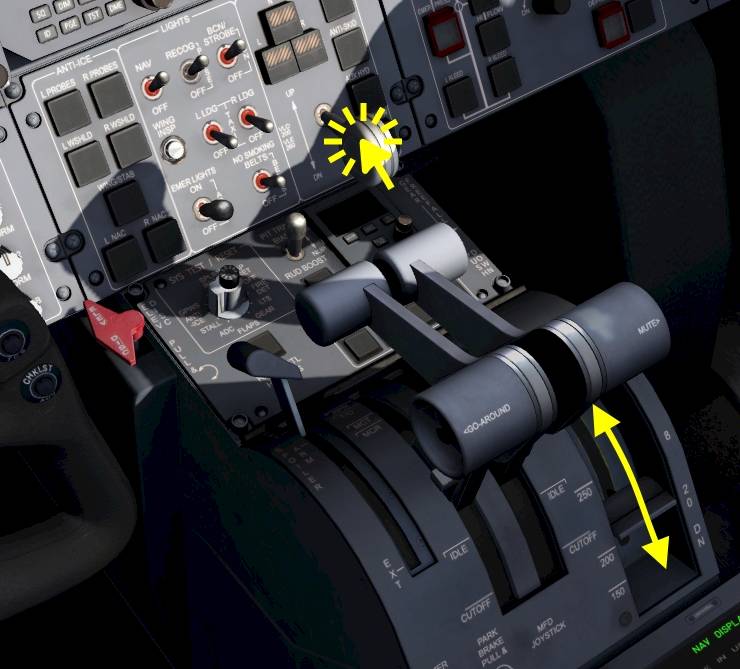
If you have to go around
At 55ft radar altitude (the white boxed number on the PFD in the attitude indicator, at the bottom) gently move your thrust levers to idle. Counter the pitch up tendency due to the engine thrust change and steer the aircraft a bit towards the ground. Softly flare the aircraft, due to its low wing it has a lot of ground effect, not much pull up is required.
Check the spoilers extend, on the EICAS you can see the spoiler position going up and in the CAS you can also read the text “SPOILERS EXT”.
Activate the thrust reversers. Use your assigned controls for this. You may use the thrust reversers up to 40 knots airspeed in this aircraft.
Slow down with the brakes and try to vacate the first taxiway after the two runways. The best visual clue are the markings on the runway. We want to take the exit just before the large solid white rectangles (beginning of the touch down zone from the opposite direction).
Welcome to Santa Barbara!
After vacating the runway to the right continue taxiing straight to the general aviation terminal (GAT).

When you turn off the runway turn off the landing and strobe lights.

On the Radio Management Unit set the ATC/TCAS to standby.

We can now reset the flight directors and clear any modes in the Flight Mode Annunciator (FMA) on the PFD.
Note - When the autopilot is engaged in flight, if you press the flight director key on the side the XFR arrow points to, the flight guidance modes will be reset to ROL and PIT basic modes. If you press the opposite side the flight directors on that side will disappear from the PFD.
Now we reached a similar state compared to how we found the aircraft at the beginning of the tutorial.
| After Landing Checklist | |||||
|---|---|---|---|---|---|
| No. | Location | Panel Name | Action | Remarks | |
| 1 | Front Panel | RMU | ATC/TCAS | STANDBY | |
| 2 | Lower Front Panel | LIGHTS | LANDING/TAXI LIGHTS | TAXI | |
| 3 | Lower Front Panel | LIGHTS | RECOGNITION LIGHTS | OFF | |
| 4 | Lower Front Panel | LIGHTS | BEACON/STROBE | BEACON | |
| 5 | Quadrant | SPOILERS | SPOILER LEVER | RETRACTED | |
| 6 | Quadrant | FLAPS | FLAP LEVER | UP | |
| 7 | Pedestal | WEATHER RADAR | WX MODE | STANDBY | |
| 8 | Front Panel | STANDBY INSTRUMENTS | STBY ATTITUDE INDICATOR | CAGE | |
Continue straight on the taxiway. You’ll find plenty of aircraft parked South of the building with the red roof, find a nice spot and set the parking brake.
Let us quickly summarize the flight that we did. At Bob Hope we prepared the aircraft for takeoff, taxied to the runway and used the FMS to guide us along the route. If you did the little sight seeing tour at the beginning I hope you got to see the Hollywood sign or at least now know where it is located. In the air we demonstrated the VOR capture and descended in vertical speed mode. The Learjet also has VNAV capability for the descent if you want to try that out, check out the Q400 tutorial, where we describe a VNAV descent for a very similar autopilot. Throughout the flight we had to manage the throttle ourselves, because the Learjet’s autopilot isn’t equipped with auto throttles. At the end we did a basic pattern in heading select mode and intercepted the ILS into Santa Barbara. I hope that this part wasn’t too complicated and that you managed to to fly the approach.
Hopefully this tutorial provided you with enough information to that you can manage your next journey in this aircraft all by yourself. You could retry the tutorial flight with the VOR capture and the Hollywood sign next to gain a bit more understanding about the navigation source selection to use it to your benefits. Or you could continue the flight northbound to San Francisco or South towards San Diego or Catalina.
If you enjoyed following this tutorial, maybe you might also have fun trying out the Dash8 Q400 flight tutorial next? There are plenty of similarities between their autopilots, the navigation source selections among other things. Once you understand the way the autopilot works in either of the two aircraft you will probably understand the other autopilot as well.
Explanations for the CRJ-900, Learjet 45, Dash8-Q400 and King Air C90GTx autopilots.
In our special tutorial for the UNS-1 FMS you will learn how to enter a flight plan for the 737-500, LJ45 and Q400 in the cockpit.
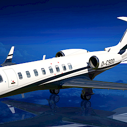
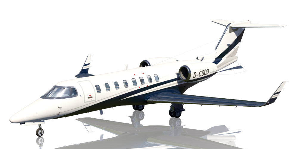
Check out the dedicated Learjet 45 page to get an overview about its features, see more screenshots and find more details about this aircraft in Aerofly FS.

We’re explaining the cockpit instruments, features and functionality of the Learjet 45 in our flightdeck guide.

The checklists used in this tutorial can be found on this dedicated page.
Find more interesting tutorials to read on our tutorials main page.