
 English
 Deutsch
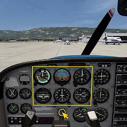
Cessna 172 Flight Tutorial
Wir zeigen Dir in diesem Tutorial in der Cessna 172, wie man das Flugzeug abflugfertig vorbereitet. Danach zeigen wir, wie man den Autopiloten benutzt, ein VOR-Radial einfängt und einen ILS-Anflug fliegt.

Welcome to Aerofly FS and perhaps your first flight in a Cessna 172. We’re going to introduce you to the basic flight instruments first before we head out for a short local flight around the airport.
Disclaimer
Please don’t apply the information that you learned in the tutorial in the real world directly without taking real world flying lessons with a certified flight instructor. This tutorial is applicable to simulator flying only.

Looking at the main instrument panel we find the classic six-pack of the most important flight instruments which we highlighted on the screenshot. In front of you you can find the control yoke which is used to steer the aircraft in the air. At your feet you can also find rudder pedals which are used to steer on the ground and to keep the nose pointing straight in the air.
Behind the yoke you can find all sorts of switches, mainly for controlling the aircraft lights.

Let’s take a closer look at the most important instruments. Take your time to inspect the instruments up close. From the top left to bottom right these are:

The airspeed indicator uses the pitot and static pressure from small openings in the fuselage and on the wing to mechanically compute the speed of the oncoming air. This is the indicated airspeed and is typically measured in knots, giving us a speed in KIAS, knots indicated airspeed.
The more airspeed that we have the more lift the wing can theoretically produce. We usually only need enough lift to compensate the weight of the aircraft when we want to fly straight and level. If we try to fly slower and slower and we will eventually reach a point where the wing cannot generate enough lift and we can no longer fully compensate the gravitational pull. Then we either start descending or if we still try to maintain altitude we will get into a stall situation and the wing will loose even more lift relatively quickly. The airspeed at which a stall happens varies depending on the aircraft weight, the maneuvers that we fly, the flap configuration and many other factors like the current engine power and propeller wash onto the wings. And because of that fact you can’t rely solely on the airspeed to stay away from a stall. For the simple case of flying straight and level we can still give some good speed estimates for the airspeed at which the aircraft will stall.
| Symbol | Description | Indicated Air Speed | Marking on A/S |
|---|---|---|---|
| VS1 | Stall speed at landing configuration | 40 KIAS | Beginning of white arc |
| VS0 | Stall speed at clean configuration | 48 KIAS | Beginning of green arc |
| VR | Rotation speed | 55 KIAS | Not marked |
| VX | Best angle-of-climb speed | 62 KIAS | Not marked |
| VY | Best rate-of-climb speed | 74 KIAS | Not marked |
| VFE | Max flaps extended speed | up to 10°: 110 KIAS | White arc ends at 85 KIAS |
| more than 10°: 85 KIAS | |||
| VC | Typical cruising speed | 90 - 120 KIAS | Not marked |
| VA | Maneuvering speed; Abrupt movement | 105 KIAS | Not marked |
| VNO | Max structural speed | 129 KIAS | Beginning of yellow arc |
| VNE | Never exceed speed | 163 KIAS | Red line |
The attitude indicator consists of three gyroscopes that maintain their attitude relative to the ground reference. The gyros can be driven by electrical motors or by a small vacuum pump attached to the engine, depending on aircraft panel configuration. Our Cessna 172 is uses a vacuum driven system.
The gyros remain in a fixed attitude while the aircraft rotates around it. Attached to them is a symbolic picture with a white horizontal line to represent the horizon, a blue sky part above and a brown earth color for the ground. You can also see several lines marking the pitch angles and bank angles to be able to read these angles in degrees.
Thin white horizontal lines mark the pitch angles -5°, -10° and -15° and thin horizontal black lines mark the pitch angles +5° and +10°.
White diagonal lines at the on the brown earth part show the 22.5° and 45° bank angles. The white dashes at the top of the instrument indicate the bank angles 0°, 10°, 20°, 30°, 60° and 90° for left and right turns.

The image on the right shows the the following situations in flight.

The altimeter is a diagram that expands and retracts as the ambient air pressure changes. It compares the pressure difference of the currently measured air pressure to a reference pressure set with an adjustment knob. The altimeter doesn’t show the altitude above sea level or above ground correctly unless it is calibrated to the current air pressure on the ground or sea level.
The correct pressure setting is given by local weather stations, automatic terminal information service (ATIS) or automated weather observing system (AWOS). In standard conditions the pressure is 1013 hPa or 29.29 inches of mercury (inHg).
The altimeter indicates the pressure difference between the set ground pressure or sea level pressure to the currently measured static air pressure. It shows the derived altitude with three needles.
The longest and thinnest needle with the triangle at the end shows the altitude in ten thousand feet increments.
The short and thick needle shows altitude in 1000 feet increments.
The long and thick needle shows increments in 100 feet.
To read the altitude correctly you have to combine these three needle indications in your head. First you read the 10k needle. In our example it shows roughly 0.4 something which is well below the ‘1’ on the scale, so we know we’re roughly at 4000ft but well below 10,000 ft and we can ignore the 10k needle in our calculation. Then we read the second needle, which in our example indicates 3.8 something. So we know we’re somewhere close to 3800ft. Lastly we read the third needle which shows 8.2 something so 820ft.
Combine all three needles: 0 x 10000ft + 3000ft + 820ft = 3820ft
The turn indicator consists of an airplane symbol and a balance ball suspended in water or other fluid types.

When the airplane wings are horizontal then the airplane is not turning at all. When the left wing tip tips down to the white marker then you are flying a turn to the left at standard rate which completes a full 360° turn in two minutes. A 180° turn will take 60 seconds and a 90° turn takes 30 seconds at that turn rate.
These standard rate turns (2 minutes for a full circle) are used in instrument flying conditions to fly standard procedure turns which can be flown relatively precisely even with this one basic instrument.
Internally the turn indicator is another gyroscope that it allowed to tilt depending on the change in heading. As the nose of the airplane yaws left and right the turn indicator shows the rate of turn of the fuselage as seen from above.
The turn indicator does not shot the bank angle of the plane and it also does not show any pitch information. These can be found on the instrument directly above it, the attitude indicator.

The second and lower part of the instrument is the balance ball. This acts just like a balance scale but the tube is slightly curved upwards to the end to make it less sensitive. The ball inside the tube will be pulled down by the acceleration of the airplane and rolls to the lowest point. When we always point our nose straight into the wind the ball will be centered even if we fly turns. It is the equivalent of the forces that you feel when you sit in the airplane yourself.
When the airplane nose is not pointing straight into the wind the fuselage and vertical stabilizer as well as the propeller all will create a side forces. Sitting in the plane we can feel that we are pushed to left and right. The balance ball then also deflects left and right. To correct this we should apply rudder input to straighten out the airplane nose. Otherwise we generate extra drag and worsen the experience for passengers. Thinking of bigger airliners you can imagine it would be very uncomfortable if the flight attendant’s trolleys suddenly move left and right and bump into the passengers right next to it. Similarly in a small airplane you don’t want all of your passengers and luggage to be flung to one cabin side like they do in a car. Unlike a car the airplane is sensitive to being loaded asymmetrically and would start to roll slowly in an uncommanded fashion.
Looking at the ball, if you see it deflected you should push more of the rudder pedal where the ball is on. If the ball is on the left you apply left rudder with the left foot. When the ball is right of center you push right rudder with the right foot.
You can “kick the ball” back to neutral with your feet.

The heading indicator is a gyroscope that maintains its attitude even if the aircraft turns around it. You can think of the compass rose being stationary while the aircraft symbol turns with the actual airframe.
The heading indicator therefor shows the direction of the aircraft nose relative to the fix gyro reference. The gyro is adjusted to the known runway heading before taking off and during the flight it can also be re-calibrated using the magnetic compass on the windscreen. Aerofly FS manages this calibration for you and the heading indicator shows the correct magnetic heading for you.

The heading indicator has a small heading bug that can be adjusted with the knob in the lower right corner
The vertical speed indicator shows the rate of climb and rate of descent by comparing the current air pressure with the pressure inside a pressure vessel. The air is allowed to flow in and out of this chamber and the needle moves according to that airflow.
With the needle at zero the aircraft is neither climbing nor descending. You are maintaining altitude for the moment.

When the needle deflects up then you are climbing. It shows the rate of climb in 100 feet per minute. With the needle pointing at +10 for example you are climbing at 1,000 feet per minute. Climbing from 2,000 ft to 4000 ft will take two minutes at that rate.
If the needle is pointing down you are descending and loosing altitude. For approach and landing as a rule of thumb you can use your airspeed in knots and divide that by 2 to give you the necessary sink-rate indication for a stable 3° approach angle. For an approach speed of 70 knots in our Cessna this yields roughly 350 ft/min. For 80 kt it’s 400ft/min and for 100 kt it’s 500ft/min. The actual rate required depends on other factors like wind speed and actual ground speed but this is a good estimate.
This concludes the basic six most important instruments on the Cessna 172.
Next, let’s talk about the engine in the Cessna 172 SP. The Cessna 172 SP in Aerofly FS has a fuel injection piston engine. The mixture of air and fuel is ignited by spark plugs.

The engine rotation speed can be monitored on the engine tachometer which shows the engine’s revolutions per minute (RPM). On the same instrument you can also see the total time that the engine has been running, similar to the total mileage indication in your car.
With maximum power, on the ground the engine usually reaches up to 2500 RPM. In the air we may have to reduce the throttle slightly to stay below the red-line limit of 2700 RPM above which we could damage the engine and/or propeller.
On the ground we aim to keep the rotation speed above 1000 RPM to keep it running smoothly and to provide enough generator power to charge the battery. At the full idle position the generator doesn’t output enough power to and you can run the risk of draining the battery.
Our Cessna 172 SP has a rather simple fixed pitch two blade propeller. The piston engine drives this propeller directly.

The engine is throttled with a black throttle lever in the center of the panel. This adjusts the amount of air and fuel that enter the pistons and the engine power changes.
Increasing the engine power will help us accelerate and fly faster or climb. Decreasing the engine power helps us to slow down and causes us to descent.

The ratio of fuel to air can be fine tuned with the red mixture lever in the cockpit to adjust the engine to the environmental conditions for maximum power output or for best fuel economy.

The spark plugs which ignite the fuel receive their electric power from two rotating magnets attached to the driveshaft that induce a current in electric coils near them. When the engine is rotating these magnetos cause the spark plugs to fire. In the cockpit we can open the two electric circuits (one for each magneto) to stop the engine ignition for each side individually. The ignition key can be found in the lower left of the instrument panel and has multiple stops.
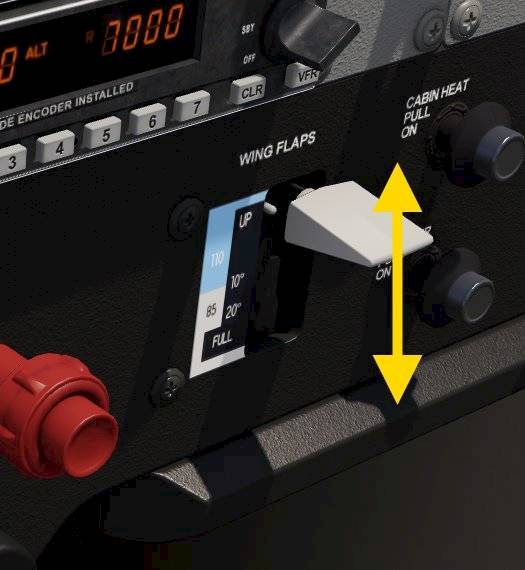
Behind the right hand yoke you can find the flap lever. This lever selects the desired flap positions: up, 10°, 20° and 30°. The more flaps you have the slower you’ll be able to fly. With extended flaps you can’t fly as fast because the drag is high and because you could also damage the flaps at high speeds. Because of the additional drag you will need more power and you cannot climb as steep and not as quickly.

On the ground, if we don’t want to push the left and right foot on the rudder’s break pedals all the time we can use the parking brake. The parking brake is a lever under the front panel between the knees of the pilot.

In the center, below the front panel you can find a large wheel. This trim wheel is rotated in the direction that you want the airplane nose to move. By rotating this wheel you can deflect a small aerodynamic trim tab on the elevator that alleviates the control yoke elevator forces.
You’ll need to trim the aircraft after you increased the speed or when you changed the engine power setting.

The electric fuel pump increases the fuel delivery pressure to the engine. This ensures a continuous fuel delivery even during abrupt maneuvers on the ground. The fuel pump is turned on before takeoff and can be turned off during flight to save wear. Before landing it is turned on again and can be turned off after safe landing. The fuel pump switch is located on the front panel in the electric switching panel often hidden by the pilot’s yoke.
The fuel pump delivers more fuel than the engine needs. The excess fuel is returned to only to the right hand fuel tank which means the left one empties a bit quicker over time. Because this could cause a significant imbalance over time you can turn off the fuel delivery from the emptier tank and only use the most fullest tank. When enough fuel has been consumed so that the imbalance no longer exist you can turn the fuel selector back to both, enabling both fuel tanks to be used.
The fuel shut of valve is positioned near the fuel selector.

Behind the pilot’s yoke there are many switches that control electric systems on the aircraft.
Remember you can click on the base of the yoke to hide it!
In a cold environment ice could form on the leading edge of the wing and on the exposed tip of the pitot tube. Blocking the pitot intake freezes the pressure in the tube and airspeed indication becomes unreliable and shows erroneous readings when the altitude is changing. To prevent ice build up the pitot probe can be heated which melts any ice.
The exterior lights of the Cessna 172 are all controlled from the switches behind the pilot’s yoke.
The light switches from left to right control:

Two rotary knobs control the brightness of the radio/panel integrated lighting as well as the glare-shield/pedestal flood illumination.

Communication with the air traffic controller and with other airplanes in the vicinity is done via radio signals. Air traffic control frequencies can be obtained from airport charts and public databases.
To tune a communication frequency in the Cessna 172 we first have to dial in the frequency and then activate it.

The Cessna 172 has two separate navigation receivers: NAV1, tuned with the upper radio panel and NAV2, tuned with the lower panel. These receivers are able to pick up signals from VOR or ILS ground stations used for instrument navigation in low visibility.
When within range the course deviation indicator shows a needle deflection, otherwise it shows red OFF flags.
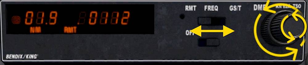
The distance measurement equipment (DME) sends a signal to the ground station and then measures the time it takes for the signal to be send from the ground station back to you. Knowing the speed at which the radio waves travel, the speed of light, the distance to the station can be computed from the time delay.

The automatic direction finder (ADF) is a device that can detect where a radio beacon is coming from. It only shows the direction to/from the station and doesn’t provide any distance information.
The transponder is a device that sends the aircraft identification and altitude to the air traffic control ground receivers. ATC can then identify you on their radar screen and provide accurate instructions or assistance.
The transponder is usually turned on before taking off and turned off after landing unless otherwise required for tracking aircraft during taxi at larger airports.
ATC assigns each aircraft a certain squawk code. The pilot enter this code into the transponder and when instructed activates the identification function which highlights the airplane on the ATC radar screens.
To set the transponder mode from off to ON or to ON&ALTitude reporting
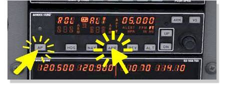
The Cessna 172 SP and Baron 58 have a basic autopilot. It features a bank and heading hold, turn to selected heading, navigation follow (VOR or ILS), pitch hold, vertical speed hold, altitude hold and approach modes as well an altitude pre-select function.
The autopilot can stabilize the heading, airspeed, altitude as well as the vertical speed. The autopilot will disconnect automatically in certain conditions:
When the autopilot is turned on it will maintain the current pitch and bank attitude. These modes are indicated with the text “ROL” and “PIT” for roll and pitch respectively.
In this mode the autopilot will attempt to keep the wings level (ROL). The autopilot switches to heading hold mode once the wings are leveled to offer a long term constant flight path but this is not shown to the pilot.
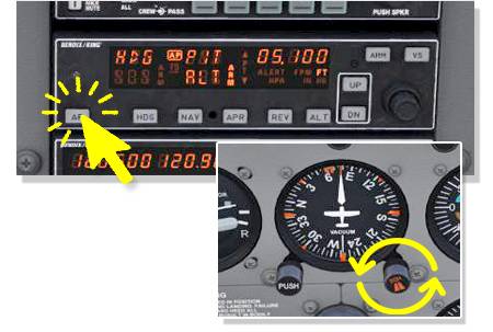
In the bottom right of the horizontal situation indicator (HSI) or heading indicator you can find the heading bug. Rotate this knob to select a target heading on the compass rose.
The autopilot can track a VOR or ILS signal. For this you need to tune a station first and then set the course and arm the capture.
Once captured the autopilot will try to center the course deviation indicator (CDI) needle.
The pitch attitude hold (PIT) mode maintains the pitch angle at the time of engagement.
You are still in control of your airspeed, make sure to add enough power if you want to climb and reduce power for the descent.

When engaged the vertical speed mode (VS) holds the current vertical speed. Note - You are in control of airspeed, make sure to adjust power.

This mode maintains the altitude at the time of engagement. The autopilot will pitch up and down to try and stay at that altitude.
The autopilot will automatically switch to the altitude hold mode when you reach the selected altitude in pitch hold (PIT) or vertical speed hold (VS) mode.

The approach mode has to be armed and captured similarly to the lateral only NAV mode. The key difference is that the autopilot will also try and capture the vertical steering from the NAV1 receiver and follow the glide slope of the ILS.
After capturing the localizer signal the autopilot arms the glide slope capture. Monitor the engagement of the lateral and vertical LOC and GS modes and reduce power to maintain the desired airspeed once the glide slope is activated.
Wir zeigen Dir in diesem Tutorial in der Cessna 172, wie man das Flugzeug abflugfertig vorbereitet. Danach zeigen wir, wie man den Autopiloten benutzt, ein VOR-Radial einfängt und einen ILS-Anflug fliegt.

Finde mehr interessante Tutorials zum Lesen auf unserer Tutorials-Hauptseite.