EC135 im Aerofly FS
Schau dir die didizierte Seite der EC135 an, um einen Überblick über die Funktionen zu bekommen, mehr Screenshots zu sehen und mehr Details über diesen Hubschrauber in Aerofly FS zu erfahren.

The EC135 is a very popular twin-engine helicopter which is used for passenger and cargo transport by the police and military, offshore operations as well as medical transport or evacuation. The EC135 can easily be recognized by the Fenestron surrounding and protecting the tail rotor and it’s four-bladed main rotor. The model comes with a low and high-skid variant which can be selected as part of the repaint in Aerofly FS.
The EC135 has a stability augmentation system (SAS) which assists the pilot throughout the flight. Together with the autopilot the helicopter is easier to fly than a conventional helicopter. That said, the EC135 is still not quite a hands- and feet-off experience and requires some pilot input during hover and as long as the autopilot upper modes are not engaged.
Two turbo-shaft engines are powering this helicopter. The engines are linked to the main and tail rotor via freewheel and main gearbox so that if one engines fails the other engine can continue to run and keeps the aircraft airborne and a safe landing is possible without the need for an auto-rotation.

Welcome to the flightdeck/cockpit of the EC135 helicopter.
In front of the pilot seat you can find the cyclic, to the left of the pilot seat is your collective pitch lever. The feet control the pedals.
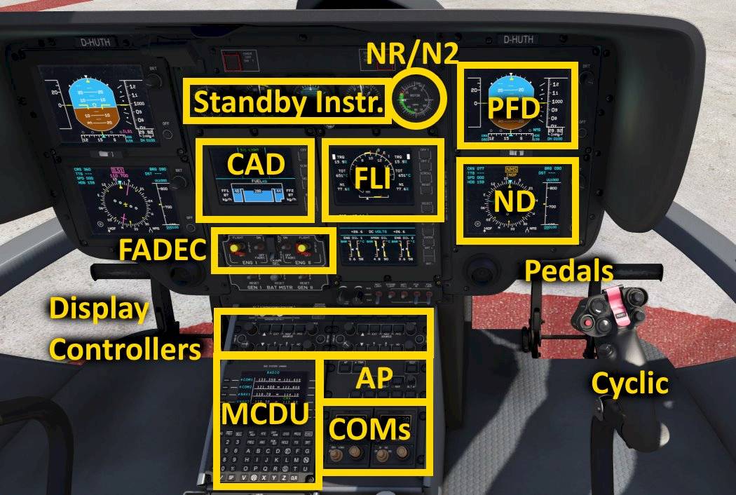
In the front-panel you can see the following instruments

The primary flight display (PFD) shows the most important flight information to the pilot.
From left to right those are:
At the bottom you can find:
The Balance indicator is installed at an angle so that it shows a correct indication when you are hovering or in forward flight.
At the top of the PFD you can flight the autopilot flight mode annunciator (FMA). The FMA shows the autopilot upper modes which is discussed in further detail in the autopilot section.


The navigation display (ND) in the EC135 consists of a compass rose with a horizontal situation indicator (HSI) in the center. The HSI shows the selected course and the course deviation for the currently selected navigation source.
Depending on the selected frequency for the NAV1 or NAV2 receiver the indications are ILS1/VOR1 or ILS2/VOR2. NMS is the route navigation of the EC135 which displays the route lateral offset and desired track.
The two bearing needles are controlled with the two bearing push-buttons.

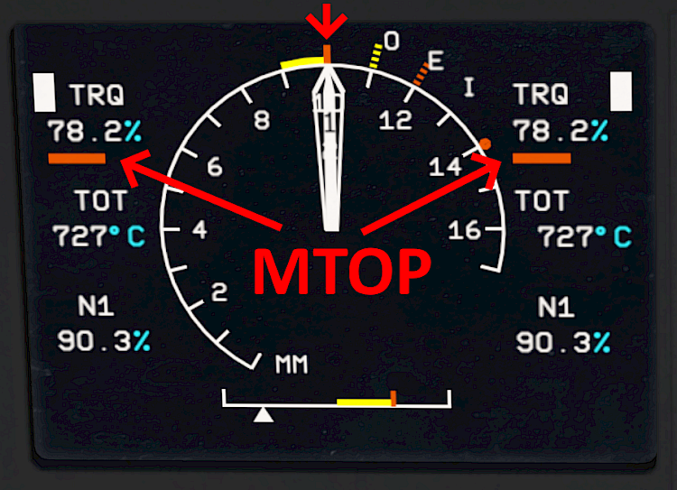
In the EC135 helicopter there are three limiting engine parameters that have to be monitored at all times:
Which ever parameter is currently closest to the maximum allowable value is then highlighted with a white box and the first limit needle shows how close to the limit the engine is currently operating.
When both engines share the load the two FLI needles (1 and 2) join. When one engine is producing less power the two needles are split. This usually happens during and right after engine start. When this happens during flight one engine may have failed.

Usually the limiting factor is the engine torque and for an all-engine-operating condition the needle reaches maximum continuous power at around 70% torque. The indication is underlined yellow.

Maximum takeoff power is reached at roughly 78% torque. Above that the indication is underlined in red. You should reduce power to avoid an over-stress situation.

The NR/ENG N2 indicator shows the rotation speed of the rotor (NR) and the rotation speed of the free power turbine speeds (N2) for each engine.
When the needles are split like in the screenshot that means that neither engine is currently providing any torque to spin the rotor.
When one of the engine needles (1 or 2) joins the rotor speed needle (R) then the engine power turbine speed matches the rotor speed and the engine is currently powering the rotor. During normal flight all three needles are joined and both engines are providing power to the rotor and tail rotor at the same time and they share the load.

The collective pitch lever of the EC135 is used to control all blade pitch angles of the main rotor together. Raising it up increases the blade pitch and causes the rotor lift to increase, the aircraft starts to climb. Lowering the collective pitch lever decreases the lift and the helicopter starts descending.
At the top and bottom of the collective pitch handle you can control the twist grip rotation for the upper and lower half of the lever. The twist grip is usually at the neutral center position throughout the entire flight. You can however rotate the twist grips out of the center position to take over manual fuel control of the individual engines. Rotating the lever with the left thumb down closes the fuel flow. The dot and N label move towards the right hand side, away from the MAX label above it. This causes the engine 1 or 2 to spool down to idle or even below idle into cut off if you twist it all the way.
There are several switches and buttons at the top section of the collective lever, easily accessible to the pilot during flight. These are the landing light switches and directional adjustment of these lights.

The cyclic stick controls the pitch and roll rates of the helicopter. A forward cyclic stick input lowers the nose of the helicopter. Pulling back on the stick pitches the nose up. Moving the stick left or right rolls the aircraft left or right.
At the top of the stick you can find several push-buttons and hat-switches.
The red button disengages the autopilot and stability augmentation system (SAS) and allows you to fly the helicopter without any stabilization.
The hat-switch below and to the right of that controls the pitch trim and roll trim. When the autopilot is engaged these buttons forward commands to the autopilot and can change the pitch angle, selected airspeed, selected vertical speed, altitude currently held or the bank angle, selected heading depending on the active autopilot modes.

In the front panel in the lower left center section you can find the engine 1 and 2 MAIN switches, labeled OFF, IDLE and FLIGHT as well as the FADEC switches.
ENG 1/2 MAIN switches:
The FADEC switch turn the FADECs off when the engine has stopped. When the engine is still running the FADEC stays on but in a less redundant operating mode.
To override the FADEC fuel flow to the engine you can rotate the twist grips on the collective pitch lever.

Navigation and communication frequencies can be changed with the Multi-Function Control Display Unit (MCDU).
As an example we will now tune a frequency for the NAV 1 receiver. All other frequencies are tuned in a similar fashion.
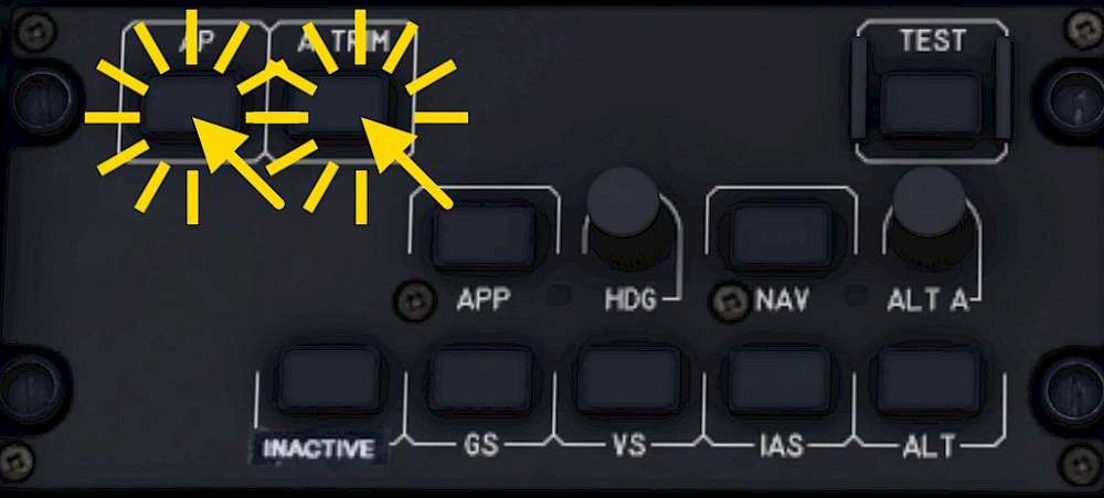
During a normal flight the autopilot is engaged before takeoff and remains on. After turning it on the autopilot maintains the pitch and bank attitude. The autopilot is engaged or disengaged with the AP push-button on the upper left corner of the autopilot panel. The AP button shows an amber OFF light when ever the autopilot is off.

With the autopilot engaged the pilot can still use the cyclic inputs as normal. Depending on the mode the autopilot will add its commands on top of the pilot commands. With the stick inputs neutral the autopilot will work as intended. With the inputs deflected the autopilot may not be able to achieve its target.
Note: On mobile devices the cyclic inputs are blocked whenever an upper mode is engaged. This allows users to put the device down without inadvertently adding commands to the autopilot. If you select the HDG mode or ALT mode for example you will no longer be able to add cyclic inputs but you are then safe to put the device down and let the autopilot do its job.

The stability augmentation system (SAS) assists the pilot throughout the flight. The SAS acts mostly as a damper and reduces undesired rotation speeds on roll, pitch and yaw. It only has limited authority.
You can disengage the SAS by pushing the red button on the cyclic. You turn it on by pushing the attitude trim button (A TRIM), the autopilot button (AP) or the hat switch on the cyclic.
Neither the autopilot nor the SAS affect your collective lever. The autopilot or SAS are not able to maintain the hover for you because of this. You always have manual collective control and you are in control of the engine power at all times.
The A TRIM button engages or disengages the attitude trim function. With the system turned in forward flight you can pull the collective lever and it will automatically pitch down to keep the same attitude. Lowering the collective will then be compensated by a pitch up command. If you turn the attitude trim off you manually have to add these compensate the physical effects of changing the collective.
Note: With the attitude trim engaged the aircraft will also automatically re-trim itself in Aerofly FS. When you turn if off you have to add manual pitch and roll trim if you want to move the center position of the stick. A force trim button is currently not simulated.
To engage the attitude system and SAS push the A TRIM button. The OFF-indication on the A TRIM button disappears. To disengage the attitude trim push the A TRIM button again or push the red button on the cyclic to disengage all stability augmentation systems.

When the autopilot is first turned on it’s in the basic attitude hold modes for pitch angle and bank angle. When no higher mode is selected the autopilot always falls back onto these basic modes.
The primary flight display shows no indications in the flight mode annunciator at the top of the display. When the pilot turns off an upper mode you can see an empty green box flashing. When the upper mode disengaged for any other reason then the box will flash in amber. The autopilot still remains on but it reverted to the basic mode.

An mode is an upper mode whenever it does more than just maintain attitude. When an upper mode is engaged it is also shown in green in the flight mode annunciator (FMA) at the top of the primary flight display (PFD).
Note: Upper modes require an indicated airspeed above 60 knots in order to operate correctly. They usually disengage on their own when you fly slower than that and they can’t be engaged at low speeds.
Some upper modes like the NAV mode or glide-slope are armed first and engage as soon as their conditions are met. E.g. the ILS can only be captured when the needle moves towards the center and doesn’t engage right after you push the button. Armed upper modes are displayed in cyan in the second line of the FMA.
The lateral upper modes are: HDG, NAV (low precision) and APP (high precision)
The vertical upper modes are: ALT, IAS, VS, ALT.A and G/S (requires APP mode to be captured)

The autopilot will bank left or right to acquire and maintains a selected heading.

An indicator on the autopilot panel lights up underneath the HDG knob. The FMA shows “HDG” in green.

Pitches up and down to maintain the airspeed at the time of engagement. When you increase collective you will start to climb. When you decrease collective input the aircraft starts to descent.

The FMA shows a green “IAS” when the mode is engaged and the IAS button on the autopilot panel lights up in green. The PFD shows a green triangle at the selected airspeed.

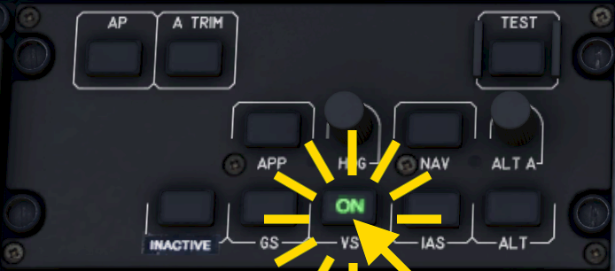
Maintains the vertical speed at the time of engagement by pitching the nose up or down. Make sure to keep the airspeed constant with your collective inputs.

Once engaged the VS button turns green and the FMA shows “VS” in green.

The autopilot pitches up and down to maintain the altitude at the time of engagement. You are in control of the airspeed with your collective inputs
The ALT button lights up green and the FMA shows “ALT” in green.

Climbs or descents towards a selected altitude with a selected vertical speed. Upon reaching the selected altitude the autopilot levels off and changes to altitude hold mode. You are in control of the airspeed by changing the collective inputs.

The green indicator next to the ALT A knob turns on and the FMA shows “ALT.A” and the selected altitude in cyan underneath.
When the selected altitude if above you the autopilot initially selects a vertical speed of +500ft/min or keeps the current vertical speed if you are climbing faster than that. When the selected altitude is lower than the current altitude it selected a descent rate of -500ft/min or keeps your current vertical speed, which ever descent rate is higher.
ALT.A will automatically change to ALT when the altitude is captured.

In the EC135 you manually select the navigation source that the autopilot follows. The selection can be changed in the control panel just above the autopilot panel.
When the navigation source is set up and shows a course deviation you can arm the navigation mode.
The FMA now shows a cyan “LOC”/“VOR” or “NAV” text in the second row. On the autopilot panel an amber “A” lights up on the NAV button to show that the mode has been armed. When the needle moves to the center an the autopilot is able to capture it the signal the mode activates on it’s own and the indications change to a green “C” on the panel and a green “LOC”/“VOR” or “NAV” on the FMA.

Depending on the selected navigation source the approach mode either follows a localizer or the route’s RNAV approach.
The autopilot APP button shows an amber “A” and the FMA shows a cyan “LOC” or “NAV”, depending on the source. The aircraft then captures the signal and follows it laterally and the button indication turns to a green “C” and the lateral mode on the FMA also turns green.
When you so desire you can now also arm the glide-slope mode for the full approach.
When a glide slope signal is received and it can be captured the autopilot starts following it.
This checklist is abbreviated and NOT suited for real world flight. Use for flight simulation purposes only!
Check for a full needle deflection on the NR/N2 display for all three needles.
Monitor as N1 increases, TOT rises, engine oil pressure increases, NR and engine N2 are rising, rotor spinning. Let the rotor speed stabilize to around 72-74%.
Monitor engine 2 start and let it stabilize, too.
Check instruments and set them as desired/neccessary.
Monitor rotor acceleration to at least 97% NR.
Check that NR/N2 indicates 100% and that both FLI needles have joined.
Perform a standard approach to 50ft above ground
Shut down all unnecessary systems.
Monitor engine and rotor deceleration.

Have fun and safe flights!

Schau dir die didizierte Seite der EC135 an, um einen Überblick über die Funktionen zu bekommen, mehr Screenshots zu sehen und mehr Details über diesen Hubschrauber in Aerofly FS zu erfahren.

Finde mehr interessante Tutorials zum Lesen auf unserer Tutorials-Hauptseite.