 English
 Deutsch
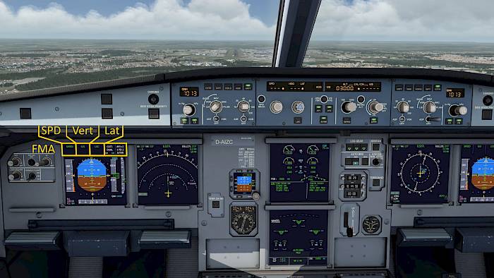
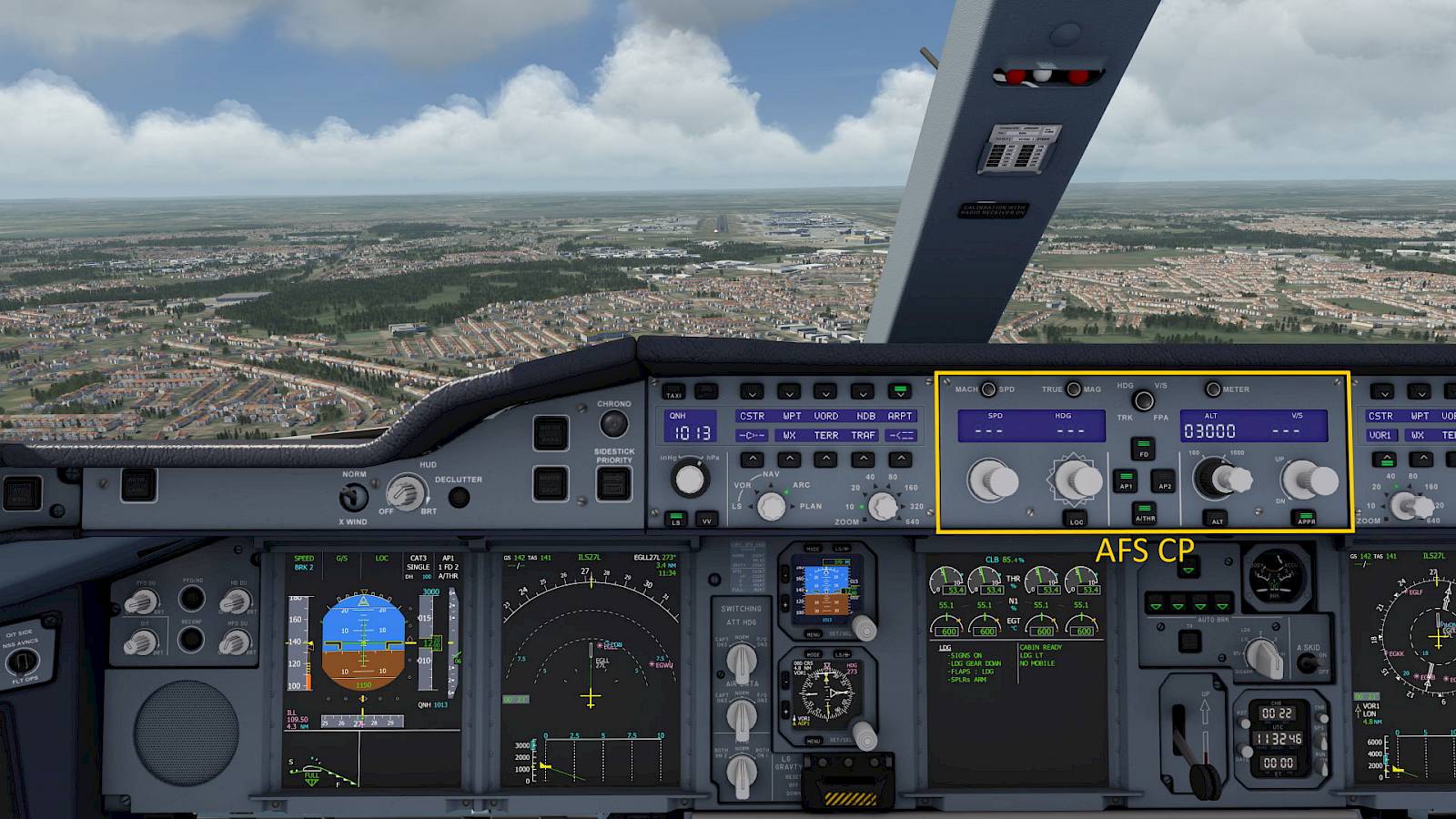
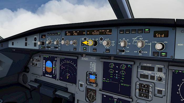
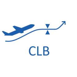
Auto-Flight-System Control-Panel (AFS CP)
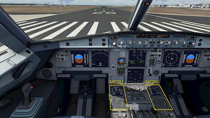
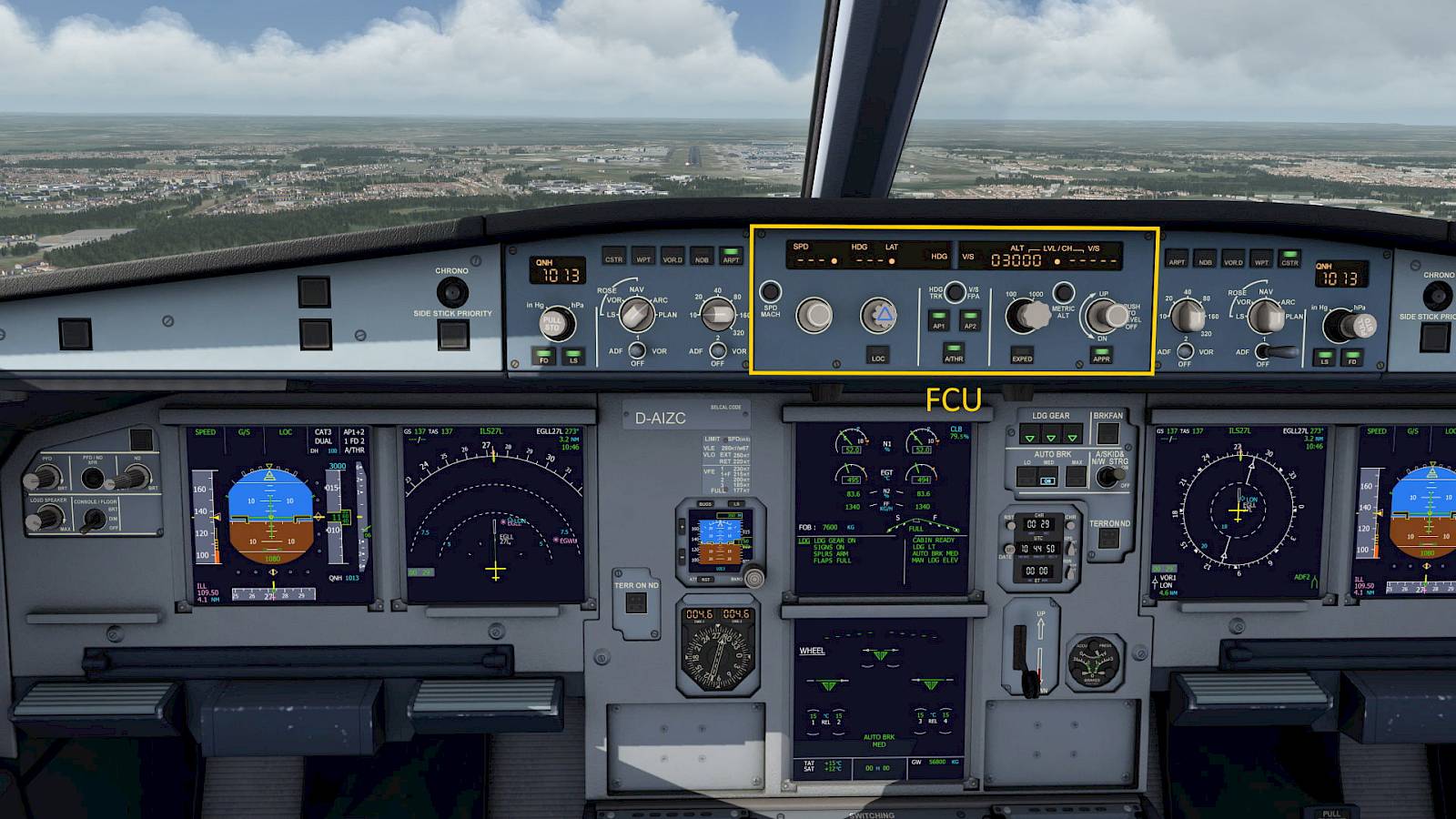
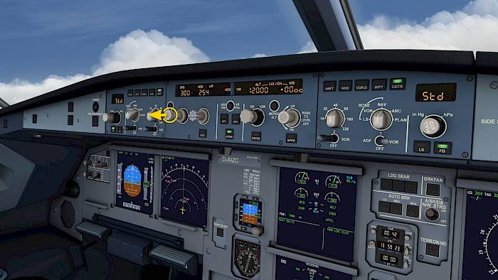
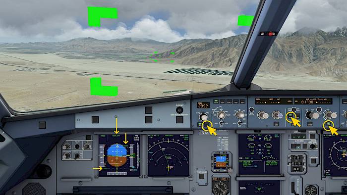
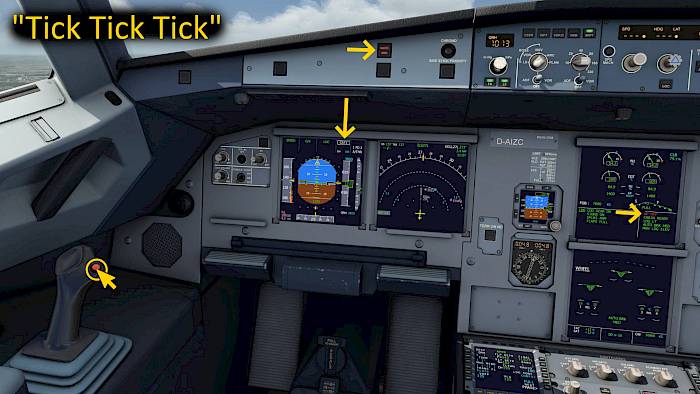
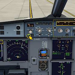
The Flight Control Unit (FCU) is a box in the glareshield, right in the center of the flight deck. It contains of two EFIS control panels, one for each pilot, and the Auto-Flight-System Control-Panel (AFS CP). The latter is the interface to the autopilot with knobs and buttons to activate modes of the autopilot.
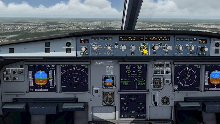
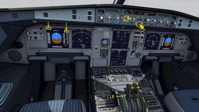
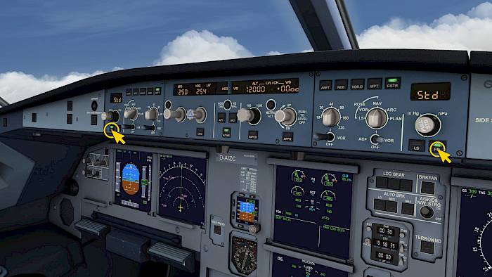
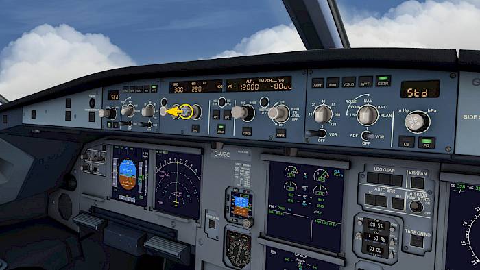
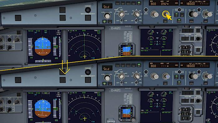
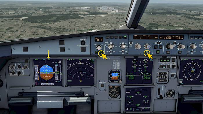
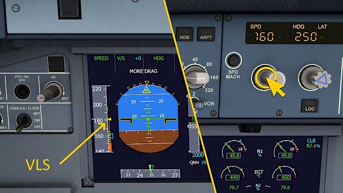
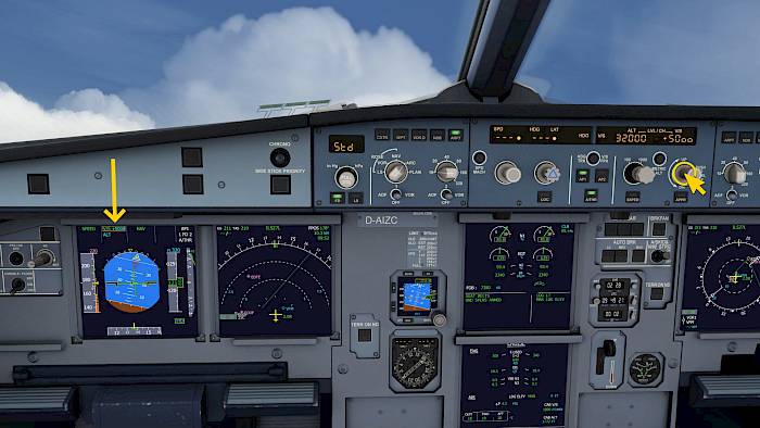
From left to right the knobs on the autopilot control
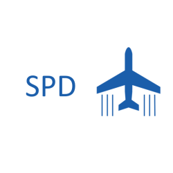
- Speed
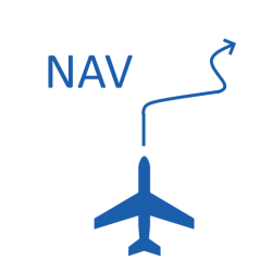
- Direction/Heading
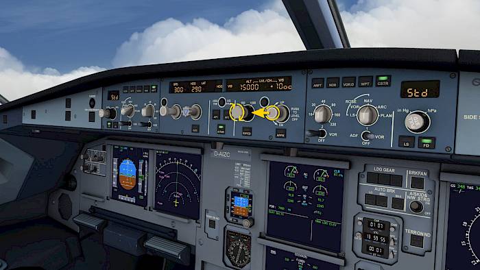
- Altitude
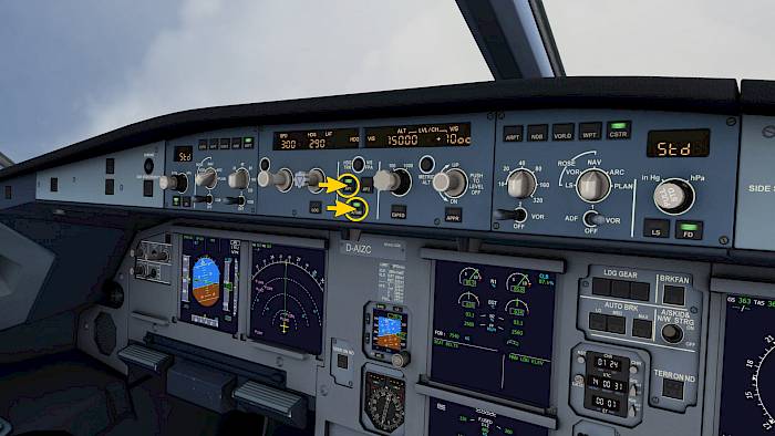
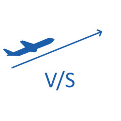
- Vertical Speed
These knobs can be pushed and pulled and there are also buttons next to the knobs to activate specific modes.