IPACS

Boeing 737 NG Full Flight Tutorial

Welcome to the Boeing 737-900ER

In this tutorial we’re going to perform a flight from Hamburg (EDDH) to Amsterdam (EHAM) using the 737-900ER in Aerofly FS.

In this tutorial we’re going through the full preflight procedures of the 737 NG, get the 737 ready for departure for our flight and then perform the full flight, approach, landing and shutdown. We guide you through the necessary steps and show you how to start the engines, prepare the systems and how to prepare the flight management computer (FMC) using the control display units (CDU). And we are going to show you how to tune the navigation radios, use the autopilot and the other systems on board this very complex and very detailed airliner.

Briefing

Navigation Route

EDDH 23 BASU2B HOP NORK2A I18C EHAM

You can easily create the navigation route using the Aerofly FS navigation menu. Or you can use the CDU in the cockpit as we describe further down.

  • Set EDDH as the origin with runway 23 for departure and BASU2B as the departure.
  • Add HOP as an intermediate waypoint (optional)
  • Set EHAM as the destination airport with ILS 18C and the NORK2A arrival
  • Set a cruise altitude of 28,000ft.
How to Create a Flight Plan?

Weather Conditions

  • Time 11:30 UTC
  • Wind weak and from SW, 220° 5KT
  • Few cumulus clouds at 10,000ft

Start Location

We’re starting at Hamburg International Airport (EDDH) on the South-East apron. Please select the ‘Cold and Dark’ option to start with all engines off and without any systems running. We want to show you this process step by step.

Location Menu

Starting Cold and Dark

We start the simulation and see the 737-900ER flight deck in a cold and dark state.

Preliminary Preflight Procedure

Electrical Power On

In the overhead panel

  • Close the DC BAT switch guard which sets the battery switch on
  • If available select GND PWR to on by moving the switch forward.

If no external ground power is available you can already start the APU now as we describe later.

Rear Overhead - Left Side

In the rear part of the overhead panel

  • Set both IRS mode selectors to NAV
  • Check that the ELT switch guard is closed
  • Check that the PSEU light is off and that the GPS light is extinguished

Rear Overhead - Right Side

  • Service Interphone switch is OFF
  • Check the Engine panel has no warnings
  • Check PASS OXYGEN switch guarded and light off
  • Check FLIGHT RECORDER guarded (OFF light is normal)
  • Test the MAX AIRSPEED WARNING 1 and 2
  • Test the STALL WARNING 1 and 2

CDU Preflight Procedure - Init

Identification

When the CDU is started you will see the menu page of the CDU first.

  • Select FMC to get to the FMC pages

On the IDENT page verify the aircraft model (737-900ER), engine rating (27K pound of thrust) and navigation database cycle.

  • Click the line select key on the lower right (LSK 6R) to go to the next step: POS INIT

Position Initialization

On the POS INIT page we need to define the initial position of the aircraft for the inertial reference system (IRS). When the IRS systems have already aligned but are waiting for this initial position we will get the ENTER IRS POSITION prompt.

  • If you see the prompt ENTER IRS POSITION you can clear it with the CLR or DEL key on the keyboard

Copy GPS Position

  • From the POS INIT page use the NEXT PAGE button to see the current GPS position on the POS REF page
  • Use the left line select key next to the GPS L or GPS R field (LSK 4L) to copy the present position to the scratchpad
  • Use the PREV PAGE button to get back to the POS INIT page

Set IRS Position

  • Insert the value from the scratchpad into the empty boxes using the line select button next to it (LSK 4R)
  • Alternatively you could also use the LAST POS, the last known aircraft position to copy to the scratchpad but the aircraft may have been moved whilst being powered off
  • Optionally you can enter a reference airport ICAO code into the REF AIRPORT field on the left and then use the reference coordinates from the airport database but this is even less precise.

CDU Preflight Procedure - Optional Route

Route

The next steps to set up a route are optional. You can also perform these with the Aerofly FS navigation menu if you like.

  • From the POS INIT page use the ROUTE> button to get to the RTE page
  • On the route page insert your route origin airport ICAO code, your destination ICAO code
  • If you already know the departure runway you can type it in here as well.

Tip - If your scratchpad is empty you can click an empty field to get a suggested value pasted into the scratchpad. For example you, if you don’t know the runway yet, you can click the empty field, get a suggestion for runway 05, then paste it in to insert it.

Departure

  • Press the DEP ARR button on the CDU
  • On the DEP/ARR INDEX page select <DEP on the top left
  • Choose your departure runway on the right, this filters the available standard instrument departures (SIDs) on the left, we use runway 23 at EDDH here
  • Select a SID on the left, we picked BASU2B here
  • No departure transitions are available
  • Press the EXEC button if it is illuminated to confirm the selection and to execute the changes

Selections are collapsed to the top of the page. To deselect a SID or RUNWAY simply

  • Press the line select key next to it to clear the selection
  • Press the EXEC button if it is illuminated to confirm the change

Arrival

  • Press the DEP/ARR button on the CDU.
  • On the DEP/ARR INDEX page, select ARR> next to your destination airport (bottom right).
  • Select an approach on the right side for a runway you want to land on. We use ILS18C here.
  • Select a standard arrival route (STAR) from the list on the left. We use NORK2A.
  • Optionally, you can select an approach transition on the right-hand side. We have selected ARTIP as the approach transition.
  • If available, you can also select an Arrival Transition on the left side.
  • Execute the changes when the EXEC light is illuminated.

Activate and Execute

  • Click the RTE button to get back to the route page
  • In the lower right corner press ACTIVATE
  • When the EXEC light illuminates press the EXEC button

Your route is now the active route used by the flight management system. Any further changes to the route will light up the EXEC light and need to be executed when they are confirmed by the crew.

Check Legs

The route is most likely not connected yet between the end of the SID and the beginning of the STAR. We need to tell the flight management computer (FMC) how we want to fly between these.

If you have additional waypoints you can insert them as follows:

  • Type the waypoint identifier into the scratchpad, here: HOP
  • Insert the scratchpad at the desired location in the list

To close route discontinuities (or gaps):

  • Select the waypoint after the disco. with the left line select key next to it
  • Insert that copied waypoint name into the boxed field one row higher up
  • Press execute to confirm the change.

Legs Step Map Center

On the EFIS control panel switch to the PLAN mode for your navigation display (ND). Now, with the legs page open, you can press the line select key in the lower right to step though each waypoint individually and to preview the route.

  • On the EFIS control panel switch to PLAN mode on the ND
  • On the CDU go to the LEGS page and use the MAP CTR function to step through the waypoints
  • Adjust the ND range with the EFIS control panel or show/hide waypoints, airports, etc.

CDU Preflight Procedure - Performance

Performance Initialization

Now the aircraft needs to know some performance figures from us.

Tip - You can get these values by clicking the line select key next to the empty field with an empty scratchpad. This makes it possible to quickly insert values by just double clicking next to the fields.

  • Press the INIT REF button to go to the next initialization reference page that still needs data from us. If that is not the PERF INIT page, check that all fields are set, then press the button again.
  • On the PERF INIT page insert the zero fuel weight (ZFW), fuel reserves, cruise altitude (CRZ ALT), cost index and cruise center of gravity (CRZ CG).
  • After the CRZ ALT has been inserted the EXEC light will illuminated. When you are done with the entries push the EXEC button.

Engine N1 Limit

On the N1 Limit page we can select a lower engine rating for takeoff. This reduces the engine core temperatures which increases the engine lifespan and decreases maintenance cost.

  • Select an engine takeoff rating on the left side.

We’re staying with the default TO rating, which gives us 26,000lbf or 115.65kN of thrust from each engine. You can also select an assumed outside air temperature which tells the engine controller that is very hot. This reduces engine thrust and tear even further but needs to be calculated based on the actual conditions. For this

  • Type in the assumed outside air temperature (hotter than reality) and insert it into the top left SEL/OAT field

Takeoff Reference

At the end we set the takeoff reference fields. There are two pages available and you can change the runway conditions and other properties on the second page but we’re keeping everything on default there for now.

  • Set the takeoff flaps configuration, in our case flaps 5.
  • Insert a takeoff center of gravity to get the pitch trim reference

Once the flaps are inserted the quick reference handbook (QRH) function suggests V1, VR and V2 values for us.

  • Simply press the line select keys next to it to accept that value or
  • Manually enter a v-speed and insert it into the field

Note - After a runway change in the the route the N1 LIMIT and TAKEOFF REF values can be deleted and messages like TAKEOFF SPEEDS DELETED tell you to re-insert your values before departure.

Overhead-Panel Preflight Procedure

APU Start

Let’s start the APU now.

  • You can optionally set the left wing AFT fuel pump to on, this assists the APU fuel pump. The new 737NG and MAX don’t need this anymore but old habits don’t die.
  • On the lower section of the overhead panel locate the APU switch and move the switch to ON and then hold the switch in the START position for three seconds and release it.
  • Observe the EGT rise on the round gauge. The 737 MAX no longer has this indicator by the way…
  • When the APU has started the blue APU GEN OFF BUS light illuminates
  • Switch the APU GEN switch left and right to ON to power the respective buses with APU generator power

Overhead Scan

Now the entire overhead panel is scanned through, starting from the top left, going down in columns.

  • Check the FLIGHT CONTROL panel, all switches guarded, ALTERNATE FLAPS in OFF position
  • Set the YAW DAMPER switch to on
  • Check the NAVIGATION panel, all switches should be in normal
  • Check the DISPLAY panel, all switches normal or AUTO position
  • Check the FUEL panel. We can turn on all fuel pumps now.
  • Check the ELECTRIC panel. We already started the APU, there should not be any caution light except the two DRIVE annunciators which is normal
  • Check the EQUIPMENT COOLING is on NORM
  • Set the EMER EXIT LIGHTS switch to ARM, the not armed light should go out
  • Set the FASTEN BELTS switch to ON
  • Check the L WIPER and R WIPER switches are on PARK

Overhead Scan (Continued)

  • Turn on all WINDOW HEAT switches
  • Set the PROBE HEAT switches to OFF/AUTO, we will turn them on later
  • Set the ENG and WING ANTI-ICE to off, not needed
  • Set the ELEC 2 and ELEC 1 HYD PUMPS switches to on. Both ENG pump switches remain on but since the engines are not running they have a LOW PRESSURE light, that is normal

Set the air conditioning panel:

  • L RECIRC FAN and R RECIRC FAN switches AUTO
  • L PACK and R PACK to AUTO
  • ISOLATION VALVE to OPEN
  • APU BLEED to ON
  • ENG 1 and ENG 2 BLEED OFF

Pressurization

Please note - The simulated copilot in Aerofly FS can assist you with the pressurization of the aircraft. Leave this panel un-changed to keep the assistance for the pressurization active for this flight. If you change it then manual control is required during flight.

  • Rotate the FLT ALT knob to set the planned cruise altitude of the flight
  • Set the destination field elevation in the LAND ALT field with the knob

During flight, if you descent before reaching the altitude set in FLT ALT then you will receive a master caution AIRCOND with an amber OFF SCHEDULED DESCENT in the air conditioning panel. This lets you know that the aircraft is going to schedule the pressurization for the elevation saved at the time of takeoff instead of the LAND ALT value set by the pilot. To clear this caution:

  • Rotate the FLT ALT knob and set the altitude to the current altitude momentarily.

External Lights

On the lower right we can control the exterior lights of the aircraft

  • Set the STERILE-Cockpit indicator light switch on. This lets the cabin crew know that we are in a busy phase of flight and wish not to be disturbed
  • Set the LOGO light switch on
  • Set POSITION lights switch to the STEADY (lower) position
  • You can keep the WING, WHEEL WELL and ANTI-COLLISION lights off for now
  • Make sure the LANDING, RUNWAY TURNOFF and TAXI lights are all off

Front-Panel Preflight Procedures

Mode Control Panel (MCP)

On the Mode Control Panel (MCP):

  • Set both flight directors ON
  • Set the A/T switch to ARM
  • Set the IAS/MACH to the V2 speed from the TAKEOFF REF page
  • Set the HEADING to the expected departure runway heading
  • Set the ALTITUDE to the initial altitude
  • Set the left and right COURSE for the departure (here runway ILS)
  • Press the LNAV and VNAV buttons to arm them

Captain Front Panel

  • Perform a light test
  • Check all indicator lights, especially the TAKEOFF CONFIG, CABIN ALTITUDE and STAB OUT OF TRIM lights are extinguished
  • Set the EFIS Control Panel for departure
  • Check the flight instruments
  • Check the standby instruments
  • Set the standby RMI
  • Check the display select switches are in the NORM position
  • Check the nose wheel steering switch is guarded
  • Check the clock
  • Test the oxygen mask to the left of the seat

First-Officer Front Panel

First Officer side

  • Same as captain except for standby instruments and nose wheel steering.
  • Check GEAR lever is down
  • Check all three gear indicator lights are green
  • Checks GPWS switches are guarded.
  • Check the lower display unit (Lower DU) engine indications
  • Set the AUTO BRAKE to RTO

Pedestal Preflight Procedures

Throttle Quadrant

  • Check that the speedbrake lever is in the DOWN detent
  • Check that the flap lever is at the position that the flap indicator is showing to prevent inadvertent movement later
  • Check that the thrust reverser levers are stowed
  • Check that the thrust levers are at IDLE
  • Check both engine fuel levers are at CUTOFF
  • Check the parking brake lever is pulled and the red light is illuminated

Control Stand

Now we tune the navigation radios for departure and check the remaining systems.

  • Tune the COM frequencies using the small and large knobs on the COM device, then swap the frequency to the active side
  • Adjust the volume levels on the audio control panels
  • Tune the the NAV frequencies as described next
  • Set the ADF standby frequency using the three knobs below the standby frequency, then swap the frequency to the active side with the TFR button in the middle
  • Set the transponder (ATC, XPDR) code, you can keep it on standby for now
  • Keep the weather radar off whilst as long as we are close to the terminal

Multi-Mode-Receiver (MMR)

Let’s tune the departure runway ILS frequency, which is 111.50 MHz here at EDDH for runway 23. To tune an ILS, VOR Frequency or GLS Channel

  1. Select the mode in standby row (here ILS)
  2. Type in the frequency or channel (111.50)
  3. Transfer it to the active side with the swap button

If you see an ERR displayed clear it with the CLR key. Make sure only to insert valid ILS frequencies to the ILS mode and valid VOR frequencies to the VOR mode as well as GLS channels only to the GLS mode.

Note - Don’t forget to set the course as well in the MCP left and right COURSE windows.

Before Start Procedure

  • Click the orange MASTER CAUTION light to cancel all master cautions for now
  • The CDU should display the TAKEOFF REF page, the right side can display the LEGS or VNAV for now
  • The MCP should be all set with both flight directors on, A/T armed, V2 inserted in the IAS window, runway heading in the HEADING window, initial altitude set, course set on both side for the departure, LNAV/VNAV armed.
  • The Primary Flight Display (PFD) shows in the flight mode annunciator in white: ARM, LNAV, VNAV
  • The PFD already shows the LOC and G/S deflections which is a good sign that we tuned the NAV receivers correctly
  • The TCAS OFF text in the lower right of the ND reminds us to switch on the transponder later on.
  • N1 limit on the EICAS screen also match what we set earlier.
  • The two LOW OIL PRESSURE indications on the EICAS are normal.
  • The indications on the lower display unit (lower DU) are normal.
  • A quick overhead scan should show no amber lights except the two DRIVE and two LOW PRESSURE lights from the hydraulic pumps. If we missed anything please set the respective system ON now.
  • The flight deck door is closed, the STERILE cockpit switch is on, everyone in the cabin is seated. We’re cleared for push and start.

We are now all set and can start our engines.

Engine Start

Initiate Start

  • Set the PACK switches to OFF
  • Set the ANTI COLLISION light switch ON
  • Rotate the ENGINE START switch for ENG #2 to GRD (ground start)
  • On the EICAS display you should see an amber START VALVE OPEN light and an engine N1 rotation

Introduce Fuel

  • Check the lower display unit (lower DU) for engine N2 rotation
  • At 25% N2 move the engine fuel lever (switch) from CUT OFF to the IDLE position
  • Monitor the EGT on the EICAS
  • Monitor the N1 and N2 accelerations

Spool Up and Starter Cut-Out

When the engine becomes self sufficient the start valve closes and the starter cuts out. You can hear the start switch click back to OFF/AUTO when the engine reaches about 56% N2. It then stabilizes at around 60% N2 and 20% N1.

Repeat for the other engine.

After Start Procedure

PACKs On

We now set the pneumatic air-conditioning kits (PACKs) on to supply fresh air to the passengers and to allow cabin pressurization later.

  • APU BLEED off
  • ISOLATION valve close
  • ENG BLEED switches ON
  • PACK switches AUTO
  • WING and ENG ANTI-ICE are not needed and can stay off

Generators On

  • ENGINE START switches to CONT for continuous ignition
  • GEN 1 and GEN 2 switches ON so that the engines generators provide their respective electric buses with power
  • Turn off the APU by moving the APU switch to OFF

The APU typically cools down for about 60 seconds because we used APU bleed air which is very demanding.

Set Takeoff Flaps & Trim

  • Move the flap lever to the 5 position
  • Observe the flap indicator. it should indicate 5 as well

The leading edge flaps (LE FLAPS) will transition to the extended position now. This can be seen on the indicator lights below the flap indicator.

  • Move the pitch trim to the calculated pitch trim position as shown on the TAKEOFF REF page. In our case 5.5 units.

Flight Control Check

  • Press the MFD ENG button to move the engine indications to the compressed format on the upper screen
  • Press the MFD SYS button to display the system page on the lower display unit

Move your control inputs for elevator, aileron and rudder through their full range to check if they are working.

  • Press the MFD SYS button again to blank the lower screen.

Recall

When the master caution button is pressed any active caution light in the master caution panel is extinguished. This is good in case of an abnormal situation because it allows you to accept certain failures, go through the necessary procedure and then clear the indication. When a new caution appears then a new master caution is triggered and the light illuminates.

We now want to make sure that no cautions are hidden though. To clear the previously hidden cautions we push the recall button.

Recall (Continued)

  • Press the annunciator area either on the left or on the right side (does not matter) to recall any master cautions that are still active.

If no master caution light appears, as shown here, then you are all set, all systems are operational.

If there are still cautions active check if you have missed anything, scan the affected panel for any amber lights and turn on that system.

Before Taxi Procedure

Set External Lights

  • Turn on the TAXI light
  • Set on the STERILE, LOGO and ANTI COLLISION lights
  • Set the POSITION STROBE switch to the STEADY (forward) position
  • Set both ENGINE START switches to the CONT position to enable continuous ignition during takeoff

Release Parking Brake

Check that the ground equipment around you is clear. We are ready for taxi.

  • Click the parking brake lever to release the parking brake. The red light should be extinguished.

Taxi Route

  • Make an immediate right turn, continue straight for a bit.
  • Then turn right and follow the taxiway in front of the main terminal buildings.
  • Continue straight and hold short in front of runway 23.

Before Takeoff Procedure

Entering the Runway

Set the other external lights on

  • LANDING lights on
  • RUNWAY TURNOFF lights on
  • POSITION & STROBE to the upper position

Transponder TA/RA

  • Rotate the transponder mode selector to TA/RA

In the TA/RA mode both traffic advisories (TA) and traffic resolution advisories (RA) are enabled. Below 1000ft the TCAS will only create traffic advisories only, as can be seen on the navigation display in the lower left corner (TA ONLY).

Line Up and Wait

Taxi onto the runway 23 and line up with the runway centerline.

  • Check that the MCP heading is set to your departure runway heading
  • Check that the MCP altitude is set to the correct initial altitude
  • Check that the LNAV and VNAV lights are illuminated when you have programmed a route like us in the tutorial flight.

For this tutorial we want a heading of 230° and an altitude of 28,000ft.

Takeoff Procedure

TOGA

  • Move the thrust levers to about 50% N1 on the EICAS display
  • Let both engines spool up to that target value.
  • Only if both engines have reached that target value advance the thrust for takeoff
  • Push the small black TOGA button on the thrust levers to engage the AUTO THROTTLE

Check your primary flight display. The flight mode annunciator (FMA) at the top should now read:

  • N1, HDG SEL, TO/GA in green
  • LNAV/VNAV in white

VR

Maintain the runway centerline with rudder inputs. When you reach the rotation speed (VR) as shown on the primary flight display (PFD):

  • Slowly raise the nose of the airplane and pitch to about 10 degrees
  • As you lift off continue to increase pitch in a continuous motion to about 15 degrees
  • Follow the magenta flight director guidance

Gear Up

  • Click the gear lever to retract the gear or grab the lever and lift it up
  • Keep pitching up and down to maintain the flight director bars centered on the attitude indicator
  • Keep wings level
  • Engage autopilot by pressing the CMD A button on the MCP

At 400ft VNAV engages but keeps airspeed at the present airspeed.

Flap Retraction

At acceleration height, which is 1000ft for this flight and can be programmed in the FMC, VNAV commands a higher speed. As a result the autopilot pitches forward to accelerate to the new speed.

  • When the airspeed rises above the green ‘5’ on the airspeed tape retract flaps to 1.
  • When the airspeed rises above the ‘1’ speed you can retract flaps to up.

After Takeoff

Note - When VNAV is not engaged you need to manually increase the selected airspeed to the flap UP speed on the airspeed indicator (“bug up”).

  • Check that the airspeed bug moves up to about 240 or 250kt below 10,000ft
  • Rotate the ENGINE START switches to OFF/AUTO
  • Set AUTOBRAKE switch to off

Enjoy the View of Finkenwerder!

We’ve mastered one of the more stressful phases in the flight. Lean back and relax, enjoy the view! Leading Hamburg behind we are now about to fly over the Hamburg Finkenwerder - this is where Airbus manufactures their airplanes.

We continue climbing. Above the transition altitude we need to change our altimeter reference from the local airport pressure (QNH) to the standard pressure. Because every aircraft uses the same reference pressure up here, regardless of where they took off from or where they are heading this makes it possible to let aircraft fly with very small vertical separation. All altitudes above the transition altitude are referred to as flight levels.

Climb

Transition Altitude

Today the transition altitude is at 7,000ft. When we pass through this altitude we can see an amber reminder below the altitude tape on the primary flight display (PFD).

  • Press the STD button on the left and right EFIS control panels
  • Press the knob of the ISFD (standby instrument)

All three altimeters should now show a green STD label next to the altitude tape.

Check Pressurization

Take a quick look at the pressurization panel. As we are climbing we want to see an increase in differential pressure on the large dial, long needle. The short needle should show a slowly increasing cabin altitude of less than 8000ft. The small bottom indicator needle should show a positive cabin rate of just 500ft/min.

If you see zero differential pressure or a cabin altitude above 8000ft:

  • Stop the climb or even descent below 10,000ft if needed.
  • Check the both engine bleeds are set on and that both packs are both operational.

FL100

We’re passing through FL100 now. Now we are allowed to accelerate above 250 knots airspeed. VNAV automatically does that for us.

  • Set off the LANDING, RUNWAY TURNOFF and TAXI light switches
  • Set the FASTEN BELTS switche to OFF if turbulence is not to be expected

Top Of Climb

We can monitor our climb on the vertical situation display (VSD) which is visible on the copilot navigation display (ND) right now.

  • To enable the VSD press the CTR button on the EFIS mode controller twice.

On the ND and VSD we see a green marker “T/C” coming up. That is the top of climb (T/C), the point at which we will have reached our cruising altitude FL280.

Cruise

We’ve reached the top of climb (T/C) point and VNAV changes to the VNAV PTH mode.

  • Observe the mode change from VNAV SPD to VNAV PTH
  • Synchronize the selected heading with the next segment on the flight plan by rotating the HEADING knob in the MCP

Yoke Checklists

Throughout the flight we can take a not what checklists we have already performed. For this the yokes on the 737 have a little checklist with a yellow marker that we can move up and down as a reminder.

  • Set the yellow checklist marker on the yoke to the next item on the list, the descent.

Navigation Radio Tuning

Tune VOR 'HOP'

Our 737 is equipped with the new multi-mode-receivers (MMR) which can tune VOR, ILS and GLS stations.

We would like to tune the VOR HOPSTEN on our route. It has the frequency 109.00 MHz and the identifier HOP.

  • Push the mode up/down arrows on the MMR to select the VOR mode in the lower row
  • Type in ‘1090’ to enter 109.0 MHz.
  • Push the transfer button on the left to activate this frequency

Tune VOR 'BMN'

On the right side we now want to tune the VOR BREMEN near Bremen Airport.

  • Select the VOR mode on the right MMR
  • Enter the frequency 117.45MHz
  • Activate the frequency by pressing the transfer button

Bremen should be within range but we may have to wait a bit for the Hopsten VOR to be picked up.

VOR Mode on ND

We can display a course deviation indicator (CDI) on an horizontal situation indicator (HSI) compass rose on our navigation display (ND) in the 737.

  • Rotate the mode knob in the EFIS control panel to the VOR mode
  • Adjust the mode control panel (MCP) COURSE window, e.g. to 220°

Now, with the station tuned and received, we can see a magenta course deviation needle, a from/to indication (currently TO) as well as the station identifier in the top right and lower right, together with a distance measurement equipment (DME) distance of currently 32.5NM.

ILS Mode Disagree

Because we currently have a VOR frequency tuned as the active frequency in our multi-mode-receiver (MMR) we can only use the VOR mode.

What happens when you switch to the ILS mode? Well the navigation display will show an error message EFIS MODE/NAV FREQ DISAGREE.

This tells us that we cannot display a VOR with the ILS mode of the navigation display and vice versa. We either need to switch to the VOR display mode or we need to tune an ILS frequency in the MMR.

With an ILS tuned the error message disappears and the display looks very similar to the VOR mode we’ve seen before.

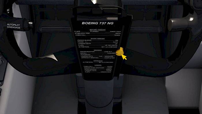
Descent Preparations

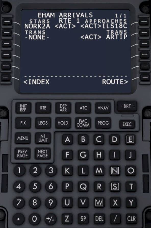
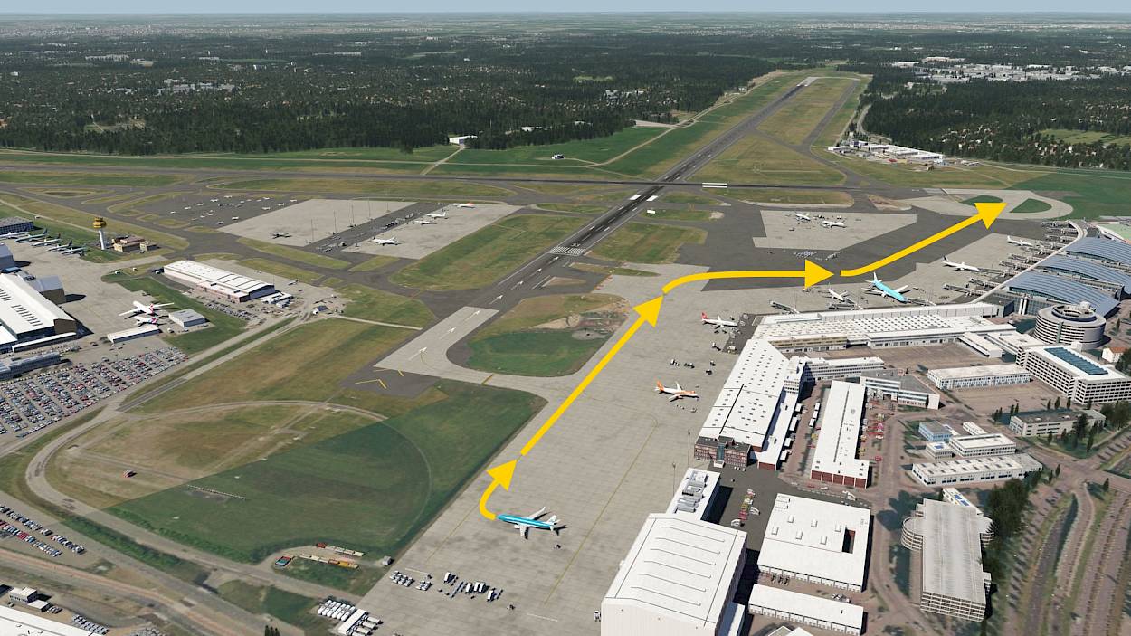
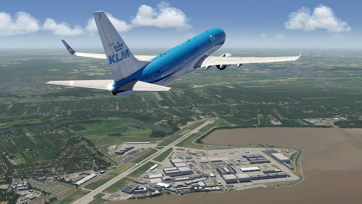
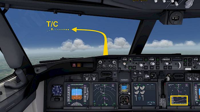
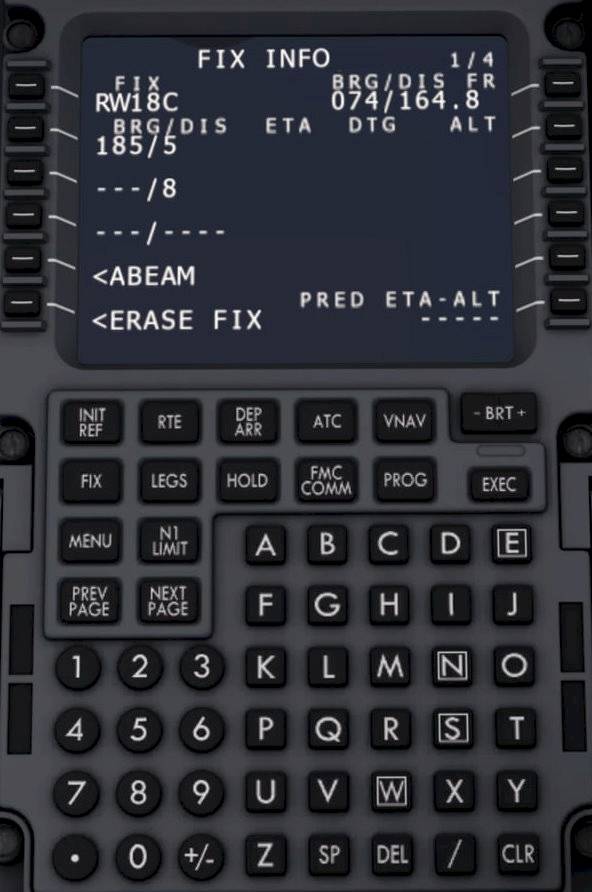
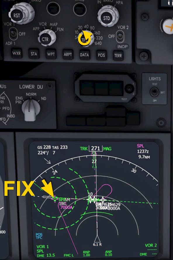
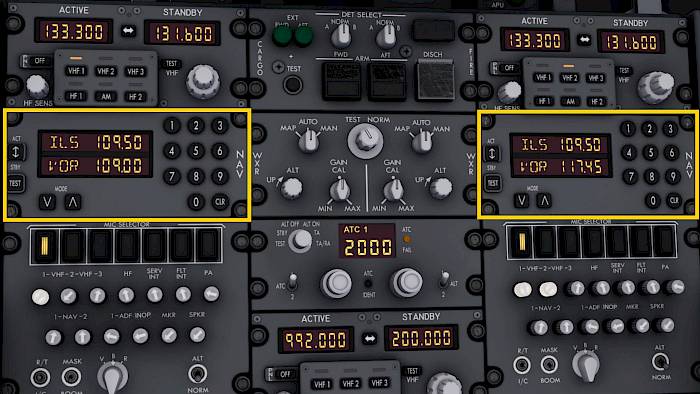
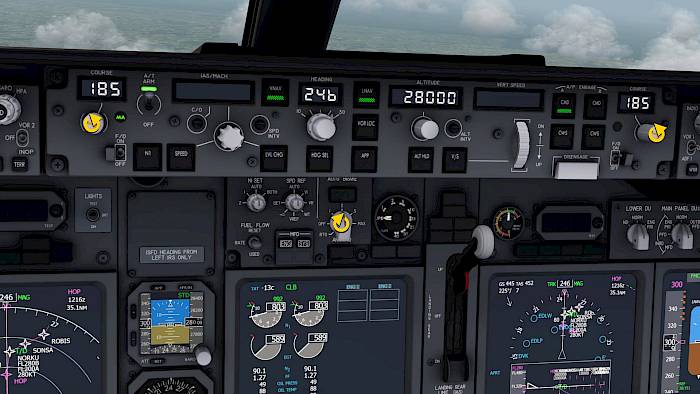
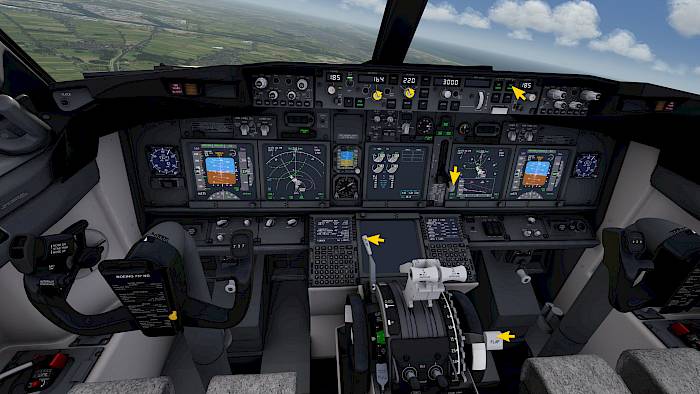
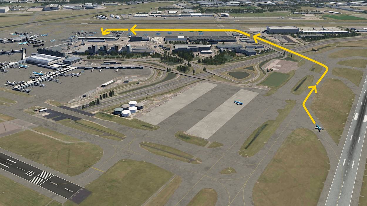
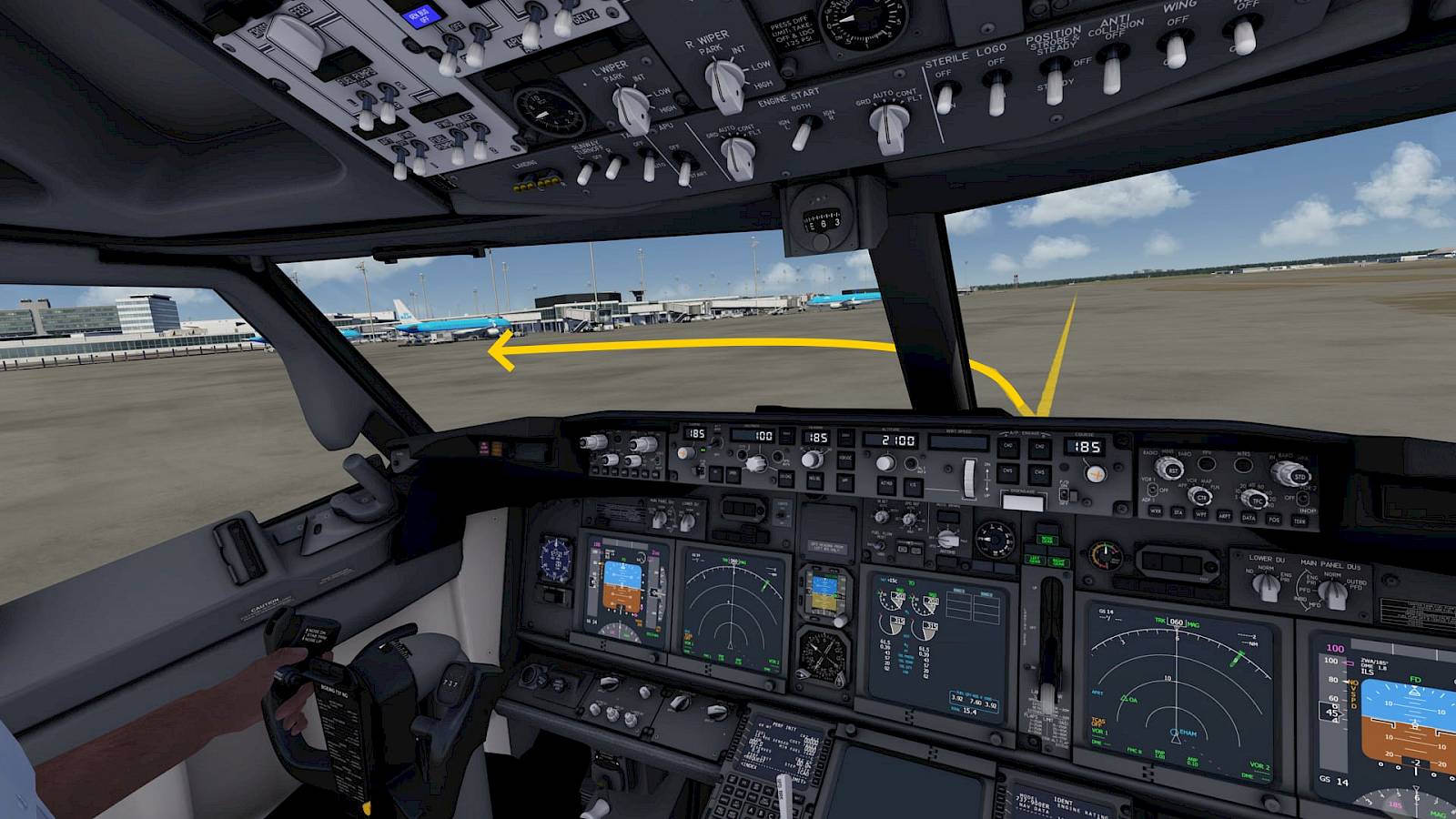
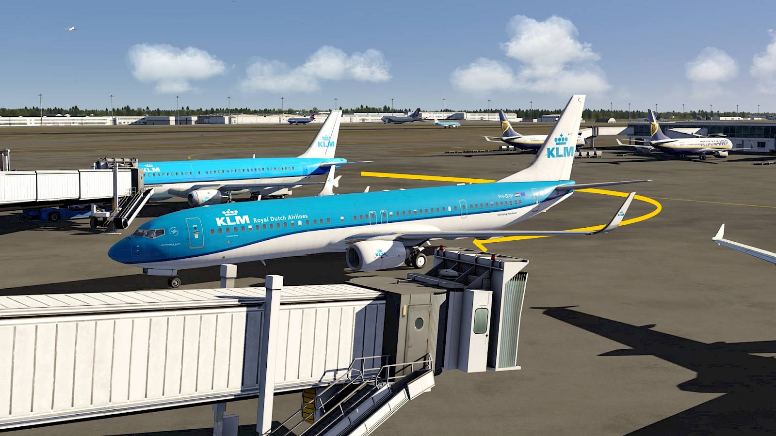
We’re flying along at 71% the speed of sound and get closer to the destination by the minute. Our plan is to fly the ILS 18C into EHAM and our route takes us over the airfield, then to the north where a procedure turn is made to intercept the localizer for the ILS 18C.

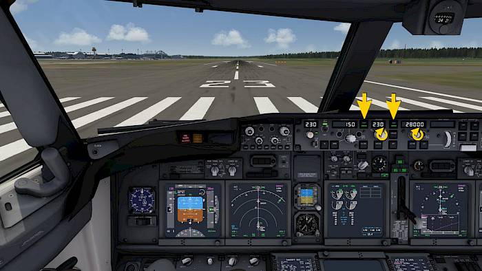
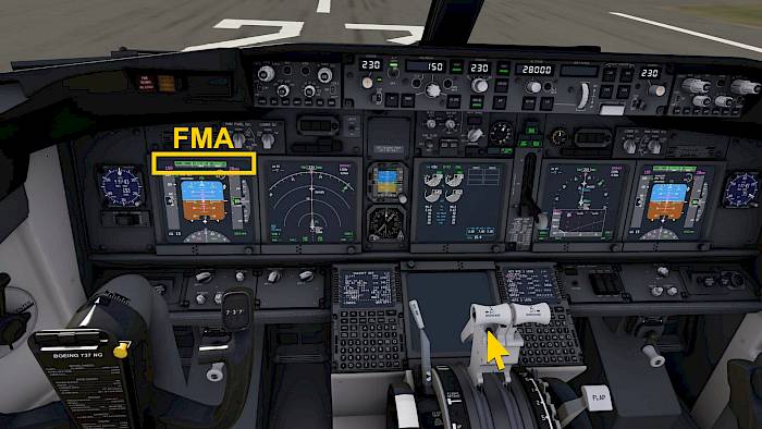
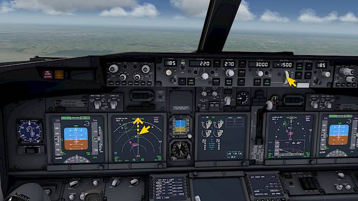
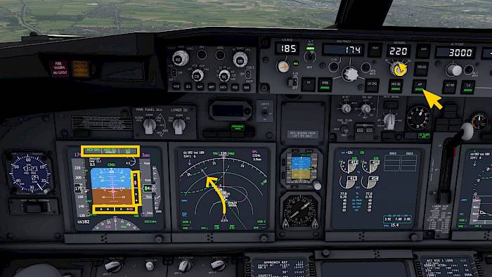
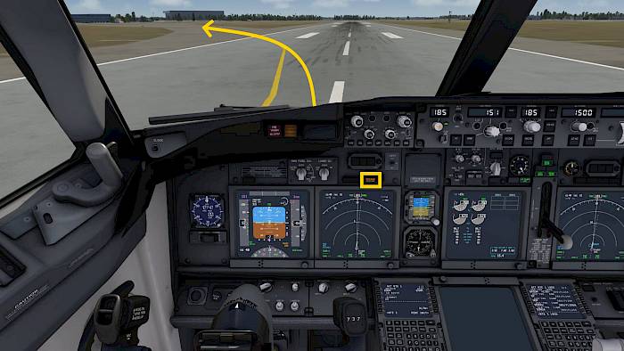
We could let the autopilot fly that with LNAV/VNAV but where is the fun in that :-) Instead we will break off the arrival and use manual heading vectors to position us for the approach. In this tutorial we’ll show you a few tricks that makes this easier.

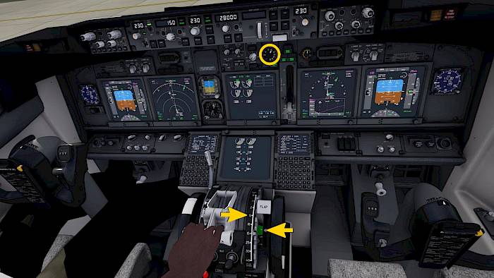
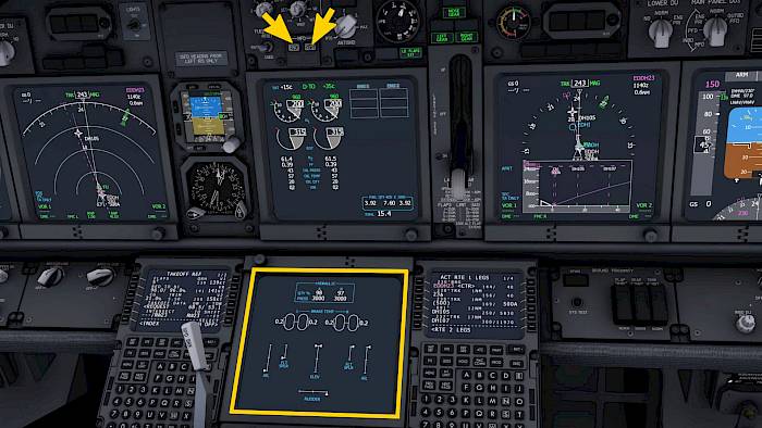
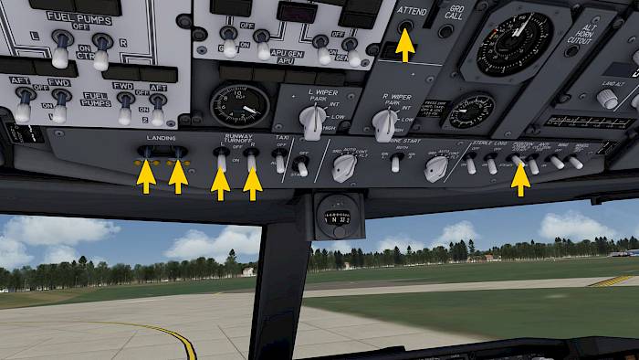
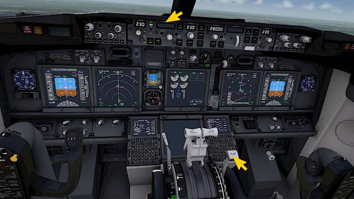
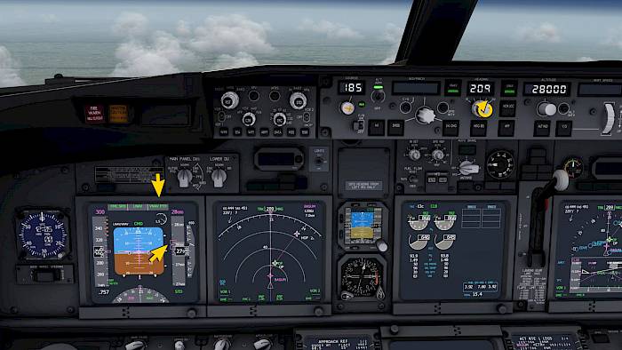
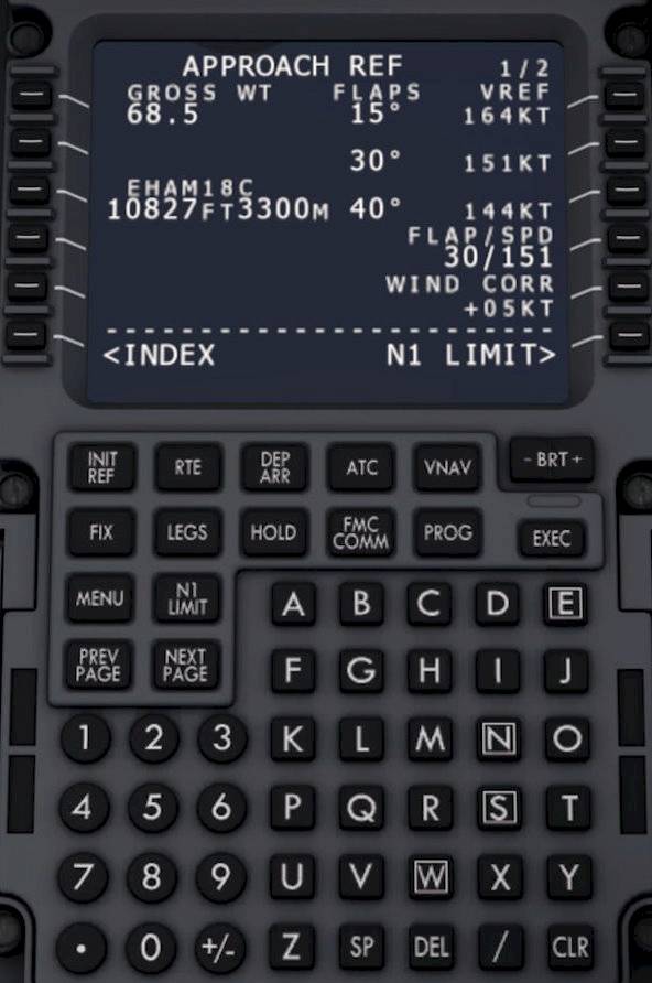
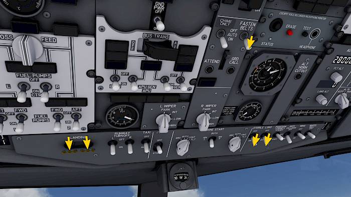
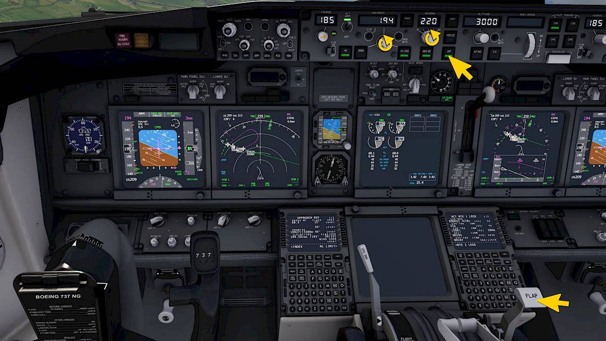
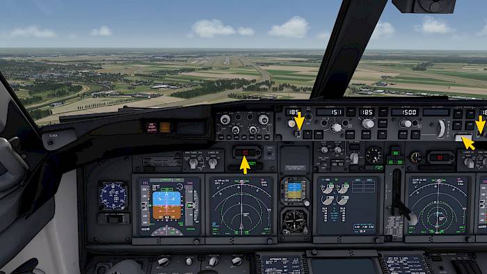
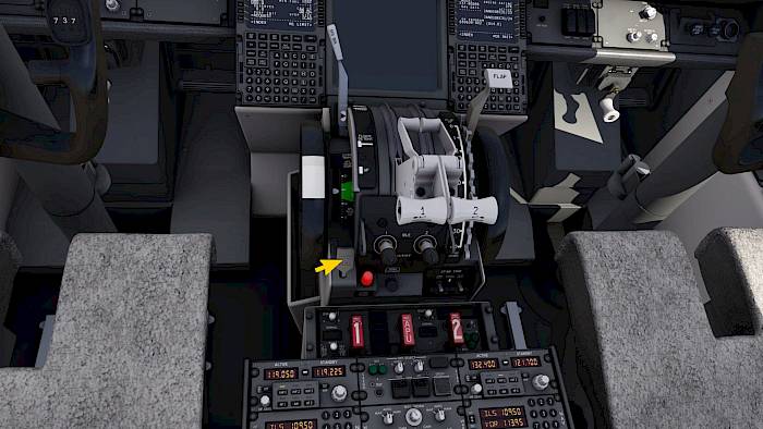
Because the runway 18C in EHAM is quite long and we need to vacate it towards the end anyway we can set up for a flap 30 approach with auto brake 2. With flap 30 instead of 40 we land a little bit faster but we also use less fuel on approach and we are quieter.

CDU - Approach Reference VREF

As we’ve said before we plan on using flap 30 for landing. Let’s insert the correct approach speed for that flap setting.

  • Press the INIT REF button to display the APPROACH REF page

On the right hand side we now have three suggested approach flap configurations and the associated approach reference speed (VREF)

  • Press the line select key next to 30° 151KT (LSK 2R), this copies 30/151 into our scratchpad
  • Insert this into the field FLAP/SPD in the fourth row (LSK 4R) to set the flap setting and VREF for our approach

CDU - Fix Info

Now we add a few navigation helpers on our navigation display (ND) that act as guide lines and distance rings.

  • Press the FIX button to open the FIX INFO page
  • Type in RW18C, which is our destination runway in the route. Insert that as FIX in the top left (LSK 1L).

Note - You can also type in EHAM or any other ICAO airport designator but you can only enter the destination runway and no other runways. There are multiple pages available if you need to add more than one navigation fix.

  • Now type in ‘185/5’ for a bearing of 185° (final approach course) and a distance of 5NM and insert that into the second row (LSK 2L).
  • In line three add ‘/8’ for a 8NM range ring.

To declutter the ND later on you can open this page and select ERASE FIX in the lower left. But let’s keep this fix loaded for now.

ND - Fix Info

The fix info that we added in the CDU will appear on our navigation displays when we get closer to our destination.

The dashed green line on the screenshot is the extended runway centerline. This is a lateral guide that points us to the runway. On final we should fly along this dashed line.

The inner dashed circle is the 5NM range ring. This is the range to the runway threshold at which we want to be fully configured for landing, gear down, flaps 30.

The outer dashed circle is 8NM away from the runway which is roughly the distance when we will intercept the glide-slope of the ILS.

Tip - When flying manually you can position yourself at the intercept point of the 8NM range ring and extended centerline, at 2500ft with a speed of less than 200kts and you should be able to capture the localizer and glide-slope with relative ease.

Descent Procedure

Tune ILS

Now we tune the ILS for our approach on the multi-mode-receiver (MMR).

  • Select the ILS mode, enter the frequency 109.50MHz and swap it to the active side
  • Do this on both MMRs

Approach Course & Auto Brake

On the mode control panel (MCP) we now have to set the approach course that matches the ILS frequency. In our case that is 185° for ILS 18C at EHAM.

  • Rotate both COURSE knobs on the MCP until their respective course window shows 185°.
  • Set the AUTO BRAKE selector to 2

Set Approach Minimums

Each approach has its individual minimum visibility criteria. For our approach at EHAM, ILS 18C we expect a good visibility but the decision height is 200ft AGL if we need it.

The approach minimums are set in the EFIS control panel.

  • Rotate the outer knob to RADIO
  • Rotate the inner knob to set 200ft on the PFD as our decision height

Top of Descent

We are approaching our top of descent on the route. You can see this on the navigation display (ND) on both sides as a green T/D marker along the route and on the vertical situation display (VSD) in the vertical profile.

  • Decrease the selected altitude in the MCP ALTITUDE window to 7000ft.
  • Perform a master caution recall by pressing the annunciator panel next to the master caution button.

Reset MCP Alt

As we get closer to the T/D point, if we have not yet changed the selected altitude a RESET MCP ALT message will appear in the CDU.

  • Decrease the selected altitude in the MCP ALTITUDE window or
  • Clear the message if you do not wish to descent yet by pressing the CLR or DEL key on the CDU keypad.

If you selected a lower altitude then VNAV PTH will remain active and at the top of descent the thrust mode changes to RETARD followed by ARM.

VNAV Descent

If you keep the selected altitude as is then VNAV ALT mode will engage and keeps the currently selected altitude and does not descent.

To resume the descent from VNAV ALT

  • Select a lower altitude in the MCP, set 7000ft for now
  • Press the ALT INTV button on the MCP (next to the knob) or
  • Press LVL CHG to drop out of VNAV and into flight level change mode

For the tutorial we decreased the altitude in time and VNAV PTH now descents automatically.

Pressurization

The pressurization is still set correctly. If we did not reach the planned FL280 before starting our descent the pressurization controller shows a OFF SCHEDULE DESCENT caution and schedules the descent back to the origin field elevation. To remove this reminder and to resume normal operation:

  • Rotate the FLT ALT value down to the current altitude if you have this caution message
  • Adjust the LAND ALT value to the planned landing field elevation

Descent on Profile

Continue the descent in LNAV/VNAV. The VNAV profile is shown next to the attitude indicator and on the right side of the navigation display. You can also see the vertical cross section on the vertical situation display (VSD). If the profile is well below you and or you are fast you need to increase drag using speed brake.

  • Monitor the airspeed and use speed brakes if you get high on profile.
  • Rotate the selected heading to match the current leg of the route
  • Select an altitude of 7000ft in the MCP

Manual Vectors

We assume that we got a short cut from ATC. We now brake off from the arrival and fly directly to the ILS intercept point.

When you reach the next waypoint after ARTIP, called “D070O” we turn right.

  • Set a selected heading of 330°
  • Press the HDG SEL button
  • Select 3000ft in the ALTITUDE window
  • Press the LVL CHG button
  • Select a speed of 220KT
  • Extend the speed brake to the FLIGHT DETENT if you are still at or above 10,000ft at this time

The autopilot now uses idle thrust and pitches up and down to maintain our selected speed. We can control the rate of descent with the speed brakes.

Descent Continues

FL100

On our descent we will pass through 10,000ft. Below this speed we need to maintain a speed of less than 250KT. We are already below 250KT, otherwise we would have to reduce the selected speed now.

  • Set on the LANDING light switches on
  • Set the STERILE cockpit switch to on
  • Turn on the FASTEN BELTS signs so that the passengers return to their seats before landing.

Transition Level

During the descent we eventually descent below the transition level. Below this altitude we switch back from STD pressure to the local airport pressure setting (QNH).

  • Push the STD button on the left and right EFIS control panel
  • Push the knob of the ISFD
  • Set a QNH of 1013hPa on all three altimeters

Adjust Descent Rate

Watch the navigation display and adjust the ND range until you see the green level off arc. This is the predicted position where we level off at the selected altitude.

  • Aim to be level before reaching the extended centerline which is visible as green dashed line from fix info or white dashed from the route destination runway.
  • Increase or decrease the speed brake extension to adjust the descent rate so that the level off arc is reached before the extended centerline
  • When the magenta glide-slope diamond on the PFD comes off the full down deflection you can move the SPD BRK lever to the down detent

Approach

We’re getting closer to the beginning of our ILS 18C approach into Amsterdam (EHAM). As we can see on the navigation display (ND) we are about 5NM away from extended centerline, which is visible as a dashed green line, thanks to the FIX INFO we set up earlier. Our green descent arc shows a level off well before reaching the extended centerline, that is ideal. A glance at the glide-slope indicator shows that the magenta diamond has moved off the full down position. We are no longer too high and can start the turn to intercept the localizer now.

  • Start the left turn to 220° by rotating the MCP HEADING knob
  • Move the SPD BRK lever to the down detent
  • Reduce to the ‘UP’ speed on the airspeed indicator (214KT here)
  • Extent flaps to position 1.
  • Reduce to the ‘1’ speed (194KT here).

ILS Approach

Localizer Intercept

Look at the primary flight display (PFD). The localizer diamond shows a deflection to the right and the glide-slope is just barely above us, this is great.

Let’s intercept the localizer to capture the ILS for the approach. We’ve already set the intercept heading using the HEADING knob. If you made the turn early or late you may have to adjust the selected heading. Try to intercept the extended centerline before the dashed green 8NM range ring.

  • Adjust the selected heading if needed
  • Push the APP button in the MCP to arm the VOR/LOC and G/S modes.

The flight mode annunciator (FMA) should now show VOR/LOC and G/S armed in white.

Gear Down, Flap 15

When the flight mode annunciator (FMA) shows VOR/LOC in green the autopilot is capturing the localizer. Once the glide slope comes down towards the center the glide-slope (G/S) mode activates as well.

Time to select the gear down and slow down further.

  • Select the gear down
  • Set flaps to 15
  • Reduce speed to the ‘15’ speed (164KT)
  • Rotate the selected HEADING to match the approach course of 185°
  • Engage the second autopilot by pressing the CMD B button in the MCP

Lights & Start Switches

  • Rotate both ENGINE START switches to CONT
  • Set the RUNWAY TURNOFF and TAXI light switches ON
  • Verify the landing gear is down, three green lights
  • Arm the SPD BRK lever by clicking on it or by dragging it slightly aft of the down detent.
  • Check that a green SPEED BRAKE ARMED light is illuminated above the left side navigation display (ND)

We’re closing in on the inner 5NM range ring at which we want to be fully configured. So let’s do that now.

5NM, Flap 30

When we reach the 5NM range ring from the runway threshold:

  • Set flaps 25, reduce selected speed to ‘25’ speed on the speed indicator (153KT here)
  • When below max flap extension speed for our desired landing flap:
  • Set flaps 30, reduce speed to VREF (151KT here)

We’re fully established and at the correct approach speed. If you want to you can fly the approach manually. The runway is already visible in front of you. But you can also keep the autopilot engaged, it will land the aircraft for you on this runway.

Manual Flight

We decide the autopilot had enough fun already and want to take manual control.

  • Press the autopilot disengage bar in the MCP to disengage the autopilot.
  • Press it a second time to cancel the warning.
  • Press the instinctive auto-throttle disengage buttons on the thrust levers or move the A/T switch to the OFF position to disengage the auto-throttle.
  • Press the instinctive auto-throttle disengage buttons a second time or press the red flashing indicator light in the front panel to cancel the warnings.
  • Move both flight-director (F/D) switches OFF
  • Set both flight-director switches back ON

Flare

The flight director is in standby for a potential go-around if we need it.

At 20ft above the runway, as seen on the radar altimeter and heard by the radar altitude callouts:

  • Close the thrust levers
  • Pitch up a few degrees to break the sinkrate
  • Touch down without floating too long

The 737-900ER has a very long fuselage, avoid a high nose attitude to avoid a tail strike.

Reverse

After touch down the speed brake automatically deploys and the auto brake activates. Use reverse thrust to slow down without using too much brakes and to keep them cool.

  • On mobile simply pull the throttle slider aft a small fraction to engage reverse thrust
  • On PC use the assigned axes preferable or grab the reverse thrust levers with the right mouse button or the hand grip of the VR hand controller to pull them up and aft.

Vacate

When we decelerated to 60KT we can stow the reversers again. At this speed the green SPEED BRAKE ARMED light turns off and the amber SPEED BRAKE DO NOT ARM light comes on.

  • Move the reverser thrust levers down to stow the reversers
  • Keep the speed brake extended until the auto brake has slowed us down to taxi speed or less than 25KT.
  • Vacate the runway to the left using one of the high speed exits.

Manual Brakes

When the ground speed shown on the primary flight display (PFD) drops to about 20KT you can cancel the auto brakes. We now use manual brakes for the rest.

  • On mobile you can briefly pull the brake slider down to 100% and then release it.
  • On PC you can briefly press the assigned key or button for the brake to take over manual control (default key is ‘b’).
  • You can also advance the thrust levers briefly to about 50% and quickly back to idle to stow the speed brake and cancel the auto brake.
  • You can also rotate the AUTO BRAKE switch to OFF to disengage the auto brake.

Welcome to Amsterdam!

We’ve vacated runway 18C at EHAM to the left on one of the high speed taxiways and now taxi around the central terminal complex along the Southern taxiway. You can pick another parking position if you like of course.

During our taxi we will clean up the aircraft configuration, start the APU and once we have reached our parking position we will shut down the engines and turn off all systems.

After Landing

Clean Up

  • Rotate the AUTOBRAKE switch to OFF
  • Move the SPD BRK lever to the DOWN detent
  • Move the FLAP lever to up.
  • Set the pitch trim back to the 5.5 units that we had for takeoff
  • Set the selected airspeed to 100KT as an obviously invalid value for the next crew
  • Set the selected altitude to an obviously invalid value, e.g. 2100

Keep rolling and make a slight right, parallel to the runway we landed on.

Lights Off

  • Turn off the flight directors (F/D)
  • Turn off the LANDING light switches
  • Set the RUNWAY TURNOFF switches to OFF
  • Make sure the TAXI light switch remains ON
  • Set both ENGINE START switches to OFF/AUTO
  • Move the STERILE cockpit switch to OFF
  • Move the POSITION & STROBE light switch to STEADY
  • Start the APU by moving the APU switch to START, hold for 3s, then release

Transponder & Weather Radar Off

Depending on the airport policy the transponder can be required until you reach your parking position. For the purpose of the tutorial we assume this is not required here.

  • Rotate the ATC mode selector to STBY.
  • Check that both weather radar mode selectors are in the AUTO position.
  • Check that WX is not selected on any of the navigation displays, this can be changed with the WXR button in the EFIS controller.

Taxi to Stand

After crossing the bridge let’s take the next left turn and taxi to our stand at the terminal buildings. There are plenty of free parking spaces available, if you see another one that you like better you can taxi there if you want. When you enter the stand please turn off the taxi light to not blind any ground personal.

Shutdown & Securing Procedures

Set Parking Brake

We’ve reached our final stop for this flight.

  • Set the parking brake

You can either click or tap on the lever or you can grab it and pull it up and aft. In the real aircraft you would first have to depress both brake pedals with your feet and then pull the lever to hold the brake pedals.

  • Make sure the TAXI light switch off.

APU Generator On & Probes Off

When the APU has been fully started the blue APU GEN OFF BUS light turns on in the overhead panel, telling us that the APU generator is now available.

  • Set on the APU GEN switch on the left and right side
  • Switch the PROBE A and B switches to OFF/AUTO

Because our 737 is already equipped with the new AUTO probe heat the heat remains on as long as an engine is running but we set the switches anyway to not forget them later.

APU Bleed On

To enable continuous operation of the pneumatic air-conditioning kits (PACKs) we now select the APU bleed air on and the engine bleed off afterwards.

  • Set the APU BLEED switch to on

A caution DUAL BLEED appears above the panel. That is normal and acceptable at this time. We never want to operate APU bleed together with engine bleed with engines above idle power. But we have idle here.

  • Set the ISOLATION VALVE switch to OPEN
  • Turn ENG 1 and 2 bleeds off

Engine Shutdown

We have now transferred electrical power and bleed air from the engines to the APU and can turn off the engines.

  • Set the ENG 1 and ENG 2 fuel switches to CUTOFF

The lower display unit (DU) now automatically displays the engine parameters. This happens when any engine parameter is abnormal and the lower display unit was blank before. This is a great attention getter for the pilots.

Fasten Belts Off

The engines are spooling down and the passengers can now be released from their seats.

  • Set the FASTEN BELTS switch to OFF
  • Turn off the ANTI COLLISION light switch when the engine N1 has dropped to a safe level.

Check the pressurization system one last time. The differential pressure should show zero and the cabin altitude should equal the current altitude. This is required to be able to operate the doors.

Fuel Pumps Off

  • Set all six fuel pump switches to OFF

Unlike in the 737 Classic we do not need to keep the left AFT 1 FUEL PUMP switch on to assist the APU fuel pump.

In the 737-900ER we also have four AUXILIARY FUEL TRANSFER switches in the upper part of the overhead panel. These remain in AUTO. In the upper right corner of the overhead we have another set of two AUXILIARY FUEL BLEED AIR OVRD switches, these should stay in the OFF position unless there are certain malfunctions.

Electric Hydraulic Pumps Off

  • Switch off the ELEC 2 and ELEC 1 HYD PUMPS switches but keep the ENG 1 and ENG 2 HYD PUMPS set on
  • Turn off any WING and ENG ANTI-ICE switches
  • Set all WINDOW HEAT switches to OFF

Lights Off

In preparation for the full shut down we now turn off all systems

  • Turn off all exterior lights now, including the POSITION lights
  • Disarm the EMER EXIT LIGHTS
  • Turn off both the L PACK and R PACK switches
  • Turn off the APU BLEED switch and start a 1 minute timer for the APU cool down period

IRS Off, APU Off

  • Rotate the IRS L and IRS R switch to OFF
  • Turn off the APU GEN switches
  • Turn off the APU by moving the APU switch to OFF

Display Flags

Now that the inertial reference system (IRS) has been switched off the primary flight display and navigation displays show amber flags for ATT, HDG, TRK, etc. This is expected.

Because we have turned off a lot of the systems we also get a master caution light for those.

Battery Off

When we have given the APU at least one minute of time after switching it off we should hear it spool down and the EGT should cool down. When the APU is no longer running we can turn off all electric power.

  • Set the DC BAT switch to OFF which opens the switch guard and holds it open.

We're done!

We’ve reached the full cold and dark state again and if you want to you can restart the tutorial and perhaps head back to Hamburg on a second flight? Or maybe you want to fly to London next?

We hope you had fun with the 737 NG!

Many good flights, Jan

2023-11-01

Tutorials