
Table of Contents
Aerowing
Objects of the aerowing class will simulate the lift, drag and moment of an airplane wing. All these force will be applied to the Body RigidBody. An aerowing consists of up to 16 sections/“Stations”, with a minimum of two stations. Each station has its own geometry, incidence (StationIncidence) and can optionally have a flap control (StationFlap) assigned.
Other Aerodynamic classes
Stations
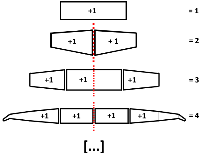
An aerowing consists of stations, at minimum 2 at max. 16 that can be parameterized. They are always indexed from right (negative Y) to left (positive Y) or bottom up (towards positive Z) if its a vertical stabilizer. Because of this indexing it is a bit complicated to mirror an aerowing. Instructions for that can be found below at mirroring.
All attributes inside an aerowing that start with “Station…” must have an identical value count equal to the count of stations for the wing. If one value of any “Station…” attribute is missing the aerofly simulator will crash.
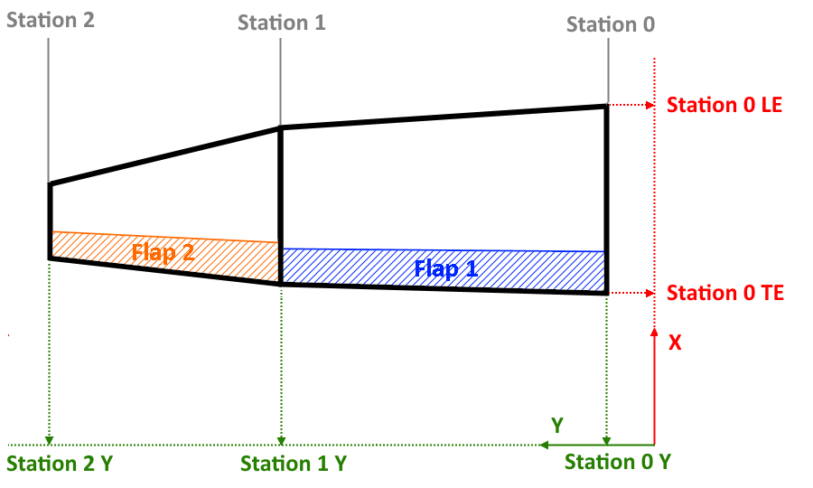
StationLE, StationTE, StationY and StationZ
Each station has X-coordinates for the leading edge (LE) and for the trailing edge (TE), a Y- and Z-coordinate.The leading edge point and trailing edge point therefore share the same Y and Z position.
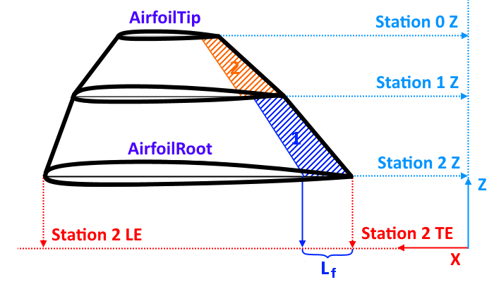
AirfoilRoot and AirfoilTip, StationIncidence
The aerowing can have two independent airfoils, one for the root section and one for the tip (AirfoilRoot and AirfoilTip). All sections in between use linear interpolated airfoils. Each section also has an attribute for the incidence of its airfoil, called StationIncidence, set in radiant.
StationFlap, StationFlapFraction, Flap0Control and Flap1Control
An aerowing can have up to two individual flaps. The flap starts from section i to and ends at section i + 1. The .StationFlap and .StationFlapFraction attribute count for that entire area from station i to station i + 1. That means the last attribute in the list for .StationFlap and .StationFlapFraction is always ignored. The default value for .StationFlapFraction is 0.2.
A.StationFlap = 0means that there is no flap for that section.
If theStationFlap = 1then the flap of that section is controlled by the =.Flap0Control= actuator.
If theStationFlap = 2then the flap is controlled by.Flap1Controllikewise.
The station flap fraction does what is says. It is a value for the fraction of the sections area that belongs to the flap.
Typical values are up to0.5 = 50%. Any value between1.0and0.0is realistic. For a horn type balance theStationFlapFractionis1.0.
StationFlapFraction = Lf / (StationLE - StationTE)
with Lf being the absolute length of the flap.
BrakeControl and BrakeArea
If a .BrakeControl is defined the values for .StationFlap may be increased by 8 so that the airbrake affects the lift of the wing-section. The .BrakeArea attribute can be used to scale the lift-loss-effect of the airbrake. For the drag force of an airbrake a different class is used: airbrake.
A flap withStationFlap = 9is controlled by.Flap0Controland also affected by.BrakeControl.
AspectRatioMultiplier
The AspectRatioMultiplier attribute of an aerowing is used to reduce the induced drag for multi-aerowing wings. For example: The F4U Corsair has wings that fold upwards. The outer wings have each an aerowing and the inner ones have as well. But in real life there is no gap in between the wings when they are folded down for flight and there is no wing vortex at that position because of that. To mimic such wings that consist of several aerowings the AspectRatioMultiplier is increased to the number of wings that build a group. For the main wing there usually is a LeftWing and a RightWing, therefor the AspectRatioMultiplier is two. The same can be said for the vertical stabilizer, which is usually simulated as two aerowings. Only a single vertical stabilizer has an AspectRatioMultiplier of one.
The AspectRatioMultiplier does not have to be an integer value. It can be decreased to increase the overall induced drag of a wing or increased to improve the aerowing's performance significantly, e.g. for gliders in high AngleOfAttack.
DownWash
To simulated the change in angle of attack due to a wing upstream or due to the self induced down wash an aerowing can experience the down wash of another aerowing object or itself.
DownWashInput
For the DownWashInput parameter the wing object's name causing the down wash is set followed by the text “.DownWashMean”.
Example:
WingName.DownWashMean
DownWashPercentage
The strength of the down wash is set with the DownWashPercentage value. Self induced down wash should have a value of 1.0 while the down wash of the main wings onto the horizontal stabilizer can have values in the magnitude of 4.0.
PropWash
Propeller, PropwashPercentage
An =aerowing= can be affected by the wash of one propeller. The .Propeller attribute points to the propeller of question and the .PropwashPercentage regulates is overall effectiveness. The .PropwashPercentage attribute can be understood as the portion of the wing that is affected by the wash. > Ergo the percentage should be above 0.0 and below 1.0. For some situations a higher value is required, for example if two propeller washes are present and the wing is entirely in the prop wash. But normally a realistic value is as low as 0.2 for a single engine aircraft.
PropwashOmega
The .PropwashOmega feels like a factor that reduces the actual “push” of the wash. If the value is higher the wash “feels” softer and the tail section of an aircraft moves more before being pushed back to neutral. A lower value “hardens” the wash.
PropwashRotation
The .PropwashRotation attribute regulates the spiraling slipstream. This effect is most noticeable on take off when the aircraft is slow and the side force of the propeller yaws the plane. Don't mistake this effect with the actual torque of the engine which is regulated with the .TorqueReduction of the AeroPropeller class or the P-Factor which can also be modeled with the AeroPropeller class using its .LateralDragCoefficient, .LateralForceCoefficient, .SideThrust and .DownThrust attributes.
Mirroring an Aerowing
Due to the indexing of the aerowing stations from the right to the left it is necessary to follow these steps in order to create a valid mirrored wing.
First the original aerowing is copied then the arrays for .StationLE, .StationTE, .StationY, .StationZ, .StationIncidence, .StationFlap and .StationFlapFraction are reversed. Secondly the .StationY coordinates are multiplied each -1 each.
Now the geometry is mirrored but the .StationFlap and .StationFlapFraction no longer apply to the same part of the wing because they count for a whole area between two sections. Therefor the array has to be shifted to the left by one. The overflow is cut away and the missing value at the most right is copied from the adjacent value.
Here are two examples: LeftWing → RightWing
                <[uint32array][StationFlap]   [ 2 1 1 ]>; // original
                <[uint32array][StationFlap]   [ 1 1 2 ]>; // reversed
                <[uint32array][StationFlap] 1 [ 1 2 _ ]>; // shifted to the left
                <[uint32array][StationFlap]   [ 1 2 2 ]>; // result
RightWing → LeftWing
                <[uint32array][StationFlap]   [ 1 2 2 ]>; // original
                <[uint32array][StationFlap]   [ 2 2 1 ]>; // reversed
                <[uint32array][StationFlap] 2 [ 2 1 _ ]>; // shifted to the left
                <[uint32array][StationFlap]   [ 2 1 1 ]>; // result
Example Code
Minimal
            <[aerowing][LeftWingAero][]
                <[string8][Body][LeftWing]>
                <[string8][AirfoilRoot][AirfoilRoot]>
                <[string8][AirfoilTip] [AirfoilTip]>
                <[float64array][StationY]           [  1.994     2.344  ]>
                <[float64array][StationLE]          [  2.7655    1.7235 ]>
                <[float64array][StationTE]          [ -4.4775   -4.4715 ]>
                <[float64array][StationZ]           [ -1.506    -1.444  ]>
                <[float64array][StationIncidence]   [  0.01      0.01   ]>
                <[float64][AspectRatioMultiplier]   [2.0]>
            >
All
            <[aerowing][LeftWingAero][]
                <[string8][Body][LeftWing]>
                <[string8][AirfoilRoot][NACA43012]>
                <[string8][AirfoilTip] [NACA43012]>
                <[string8][Flap0Control][ServoLeftAileron.Output]>
                <[string8][Flap1Control][ServoFlaps.Output]>
                <[string8][BrakeControl][ServoLeftFlightSpoilers.Output]>
                <[float64array][StationY]           [  1.994     2.344     4.424     6.382    10.7826    10.7826    13.329    13.402    16.328    16.94042   ]>
                <[float64array][StationLE]          [  2.7655    1.7235    0.625    -0.419    -2.730466  -2.730469  -4.068    -4.131    -5.626    -6.58152   ]>
                <[float64array][StationTE]          [ -4.4775   -4.4715   -4.501    -4.517    -5.768067  -5.768069  -6.492    -6.507    -7.334    -7.509945  ]>
                <[float64array][StationZ]           [ -1.506    -1.444    -1.277    -1.069    -0.7098328 -0.7098324 -0.502    -0.495    -0.269    -0.2454547 ]>
                <[float64array][StationIncidence]   [  0.01      0.01      0.01      0.01      0.01       0.01       0.01      0.01      0.01      0.01      ]>
                <[uint32array] [StationFlap]        [  2         2         2         10        10         2          0         1         0         0         ]>
                <[float64array][StationFlapFraction][  0.2       0.25      0.3       0.3       0.3        0.3        0.0       0.3       0.0       0.0       ]>
                <[float64][Flap0Area]               [0.0]>
                <[float64][Flap1Area]               [0.0]>
                <[float64][AspectRatioMultiplier]   [2.0]>
                <[string8][DownWashInput]           [LeftWingAero.DownWashMean]>
                <[float64][DownWashPercentage]      [1.0]>
                <[string8][PropwashInput]           [PropellerLeft.GetWash]>
                <[float64][PropwashPercentage]      [0.15]>
                <[float64][PropwashRotation]        [0.03]>
                <[float64][PropwashOmega]           [4.0]>
                <[float64][GroundEffectFactor]      [0.9]>
                <[float64][GroundEffectScale]       [0.8]>
                <[float64][BetaSlope]               [5.0]>
                <[float64][BetaMax]                 [1.5]>
                <[float64][RotationalChordFraction] [0.4]>
                <[bool][NoSplash][false]>
            >