
Table of Contents
Propeller
A propeller rotates around a spinning driveshaft which acts a torque onto the propeller. In the Aerofly FS 2 there are two kinds of propellers: the propeller class implements a propeller behavior in a rotating reference frame, attached to a rotating PropellerBody (rigidbody) whilst an aeropropeller uses a stationary Body and rotates itself. In all default Aerofly FS 2 aircraft only the propeller class is used.
Other Aerodynamic classes
Body and EngineRotationSpeed
A propeller object will use the velocity of its Body (rigidbody) and the EngineRotationSpeed from the driveshaft and calculate a thrust value from that and a torque value to create that amount of thrust. It then adds that force and torque onto the Body which will accelerate/decelerate the body and speed it up or slow it down over time.
Airfoil
The same airfoil class is used for the aerowing and the propeller class. Using the properties of the AirfoilPropeller it is possible to fine-adjust the torque and thrust produced by the propeller. A typical propeller airfoil is designed for a lift coefficient of about 0.5.
Geometry
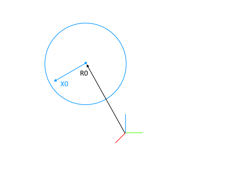
R0, X0, Y0, Z0
The position of the propeller hub is defined by the R0 position vector.
X0is the local forward,Y0is the local left,Z0is the local upwards direction.
In the example of the Extra 330 LX below the propeller is slightly angled to the right (side thrust).
Radius
The Radius of the propeller class is the physical radius of the actuator disk in meters. When converting from inches to meters simply multiply the radius in inches by 0.0254 m/inch. The radius of the propeller is of course half the diameter, which is usually given in the specifications.
Radius = 0.5 * Diameter
Pitch
The pitch of a propeller is roughly the blade angle at 75% of the radius. The pitch is the distance in meters that the propeller corkscrews through the air in one full rotation (geometrically). If a propeller pitch is given in inches multiply that figure by 0.0254 m/inch to convert it to the meter length unit used here.
With a given blade angle (alpha) and a radius ® the blade pitch is calculated to:
Pitch = 2 * pi * r * tan(alpha)
PitchControl
The name is self-descriptive here. A input can be given to change the pitch of a propeller. That way a constant speed propeller can be controlled by a governor, reversed into beta or reverse thrust or feathered.
CutOut
This is the fraction of the radius (or maybe the fraction of the area) that is not part of the propeller because of the propeller hub and spinner. The model used in the Aerofly FS 2 accounts for that blade-less portion by the CutOut scalar.
Aerodynamic Parameters
AspectRatio
The AspectRatio of a propeller is a factor that can be used to influence the rotationspeed - velocity relation ship. Physically it describes the ratio of the blade radius and the mean chord length of a blade.
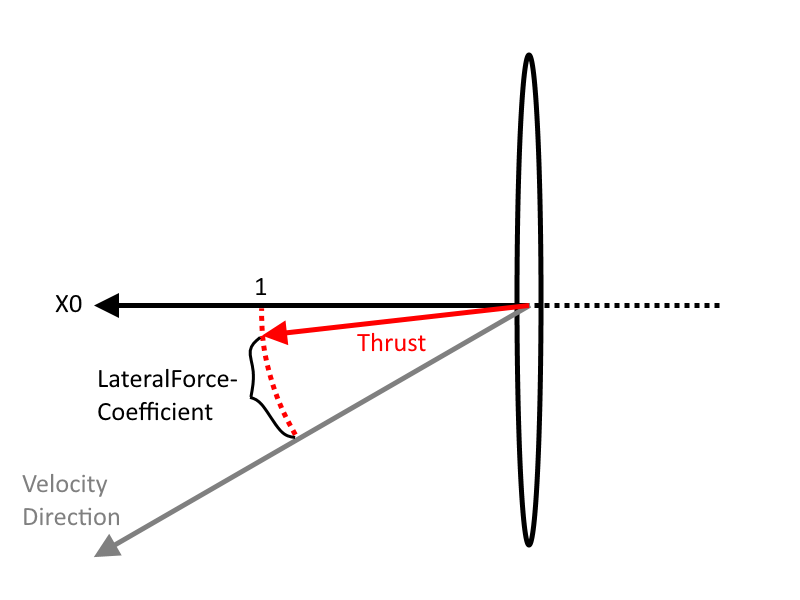
LateralForceCoefficient
The LateralForceCoefficient determines how much the thrust is pointing in the forward direction X0 of the propeller (most likely the general forward direction in an aircraft). A LateralForceCoefficient of 1.0 makes is so that the thrust of the propeller always points in the direction of X0. On the opposite side a LateralForceCoefficient of 0.0 would permit a side thrust of the propeller and its thrust is always pointing in the direction of flight.
The lower the value the more rudder is required in a static knife edge flight at full power.
A value between1.0and0.85could be considered realistic.
LateralDragCoefficient
The LateralDragCoefficient can be seen as a drag coefficient that is only applied to the lateral component of the velocity, not in the direction the propeller is pointing at. In a very high angle of attack or in a very high attitude knife edge flight a higher value creates a lot of torque around the aircrafts center of gravity and the aircraft “drags” to the side violently.
A higher value makes it much easier to enter a static torque roll. If the value becomes unrealistically high the torque roll is so stable that it cannot be stopped. Also high values tend to throw the aircraft around so that it flies backwards for a short time, not a very realistic looking behavior.
Stay below0.1to prevent high instabilities.

Example Code
C172 - Fixed Propeller
            <[propeller][Propeller][]
                <[string8][Body][PropellerBody]>
                <[string8][Airfoil][AirfoilPropeller]>
                <[string8][EngineRotationSpeed][DriveShaft.RotationSpeed]>
                <[string8][DamageOnCrash]      [Engine.Damage]>
                <[tmvector3d][R0][2.872302 0.0 0.000406]>
                <[tmvector3d][X0][1.0 0.0 0.0]>
                <[tmvector3d][Y0][0.0 1.0 0.0]>
                <[tmvector3d][Z0][0.0 0.0 1.0]>
                <[uint32][NumberBlades][2]>
                <[float64][Radius]      [0.965]>
                <[float64][Pitch]       [1.52]>
                <[string8][PitchControl][0.323]>
                <[float64][CutOut]      [0.2]>
                <[float64][AspectRatio] [7.0]>
                <[float64][LateralForceCoefficient][1.0]>
                <[float64][LateralDragCoefficient] [0.0]>
                <[float64][TorqueReduction][0.95]>
            >
Extra 330 LX - Constant Speed Propeller
            <[propeller][Propeller][]
                <[string8][Body][PropellerBody]>
                <[string8][Airfoil][AirfoilPropeller]>
                <[string8][EngineRotationSpeed][DriveShaft.GetRotationSpeed]>
                <[string8][DamageOnCrash]      [Engine.Damage]>
                <[tmvector3d][R0][1.9004   -0.0037    0.0064]>
                <[tmvector3d][X0][0.990279 -0.069798  0.000000]>
                <[tmvector3d][Y0][0.069798  0.990279 -0.000000]>
                <[tmvector3d][Z0][0.000000  0.000000  1.000000]>
                <[uint32][NumberBlades][3]>
                <[float64][Radius]      [0.99]>
                <[float64][Pitch]       [1.8]>
                <[string8][PitchControl][Governor.Output]>
                <[float64][AspectRatio] [9.0]>
                <[float64][CutOut]      [0.2]>
                <[float64][LateralDragCoefficient] [0.005]>
                <[float64][LateralForceCoefficient][1.0]>
                <[float64][TorqueReduction][0.0]>
            >