
Table of Contents
Airfoil
An airfoil is a cross section of an AeroWing. At a given angle of attack the aerowing produces lift L, drag D and a moment M. At a certain AOA (.AttachedRange) the airflow can no longer follow the contour of the surface entirely and is fully detached at the .AttachedRange + .StallRange angle. It continues to produces a significant amount of lift even beyond that high angle of attack and the lift is even increased again with higher AOA but the drag force is extremely high at that point and thus a flight in this attitude is inefficient and not practical. But its possible as some radio controlled 3D aircraft proof.
Other Aerodynamic classes
Angle of attack
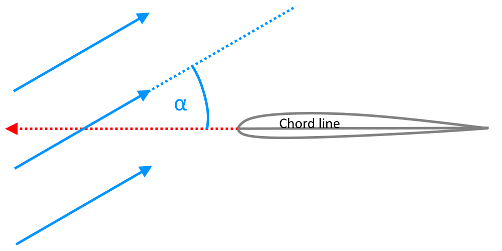
The angle of attack (also known as AOA or α (“alpha”)) is defined as the angle between the undisturbed incoming air-flow and the chord line (“the zero camber line”) of an airfoil. The lift, drag and moment of an airfoil are all functions of the angle of attack.
Attributes
AttachedRange
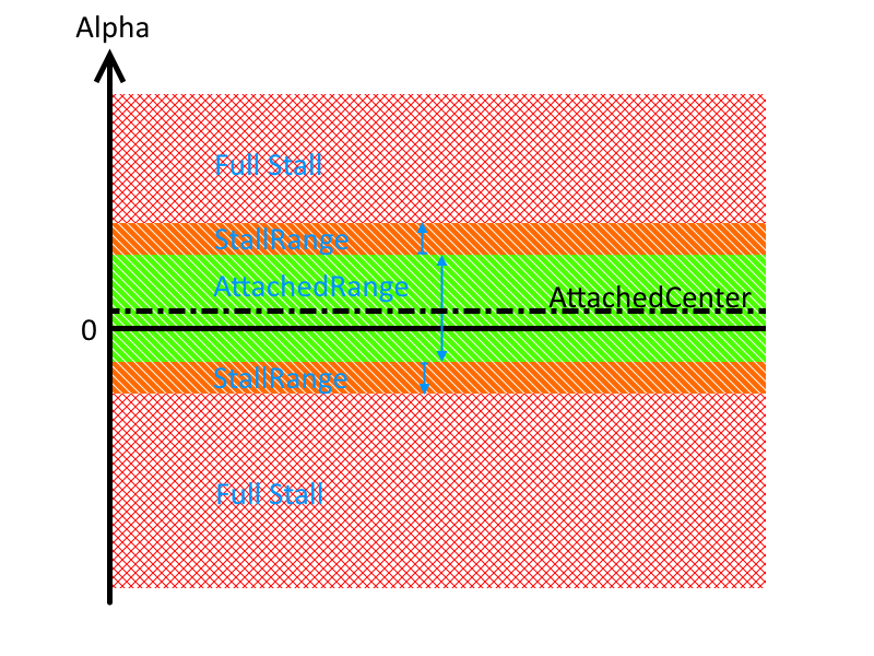
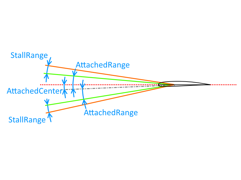
The attached range is the range of the angle of attack at which the airflow is simulated as attached to the airfoil. It reaches from -AttachedRange to +AttachedRange
AttachedCenter
The attached center creates an asymmetric attached center. Using an attribute grater than zero will offset the stall angle towards a greater angle of attack.
ClAlpha
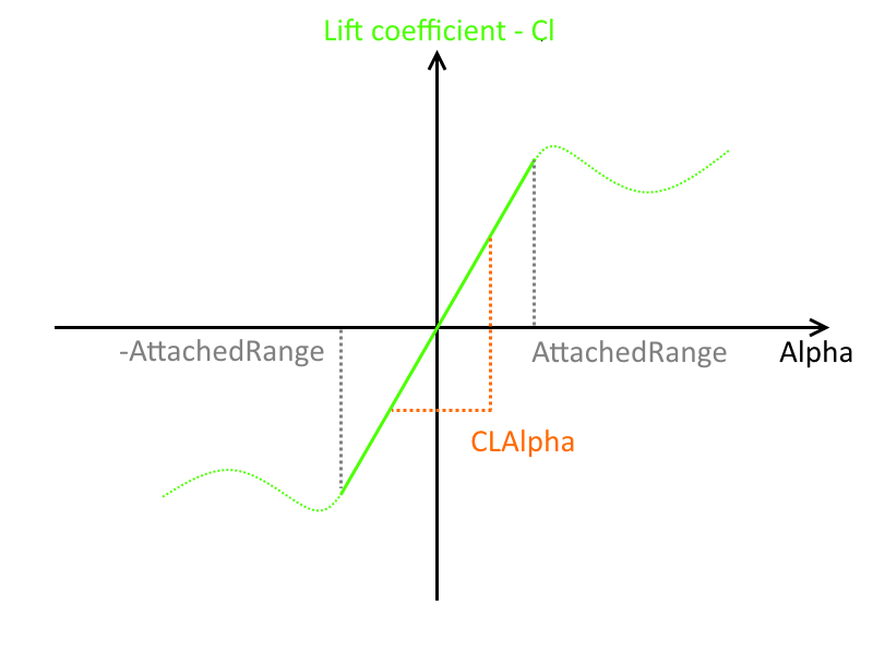
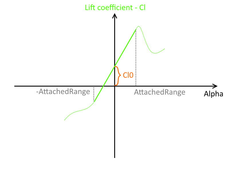
The lift coefficient Cl and momentum coefficient Cm increase linear with alpha in the Range of -AttachedRange to +AttachedRange.
The gradient of the lift coefficient in respect to alpha is ClAlpha which equals 2 * Math.Pi for most real airfoils.
Leave it at6.28(2 * pi) unless you are dealing with a delta wing
Cl0
The Cl0 parameter increases the lift coefficient when the angle of attack is zero. This is achieved in real life by giving the airfoil a camber. For symmetrical airfoils Cl0 always equals 0.
This attribute directly reflects the attitude in which an aircraft flies at high speed (low AOA). It also requires a larger down force from the horizontal stabilizer which increases the drag. It greatly affects the glide ratio.
0.3is usually a good value to start with. Jets tend to have lower values around0.1whilst slow flying airplanes have values up to0.45. Inverted airfoils have a negativeCl0and symmetric airfoils have aCl0of0.0.
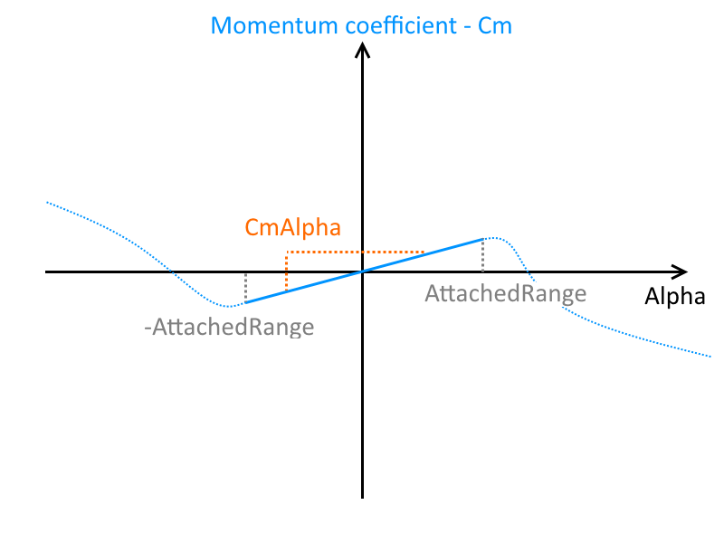
CmAlpha
The gradient of the momentum coefficient Cm is zero for symmetrical airfoils, positive for most typical airfoils that show movement of center of pressure (unstable) and negative for most airfoils with an s-bend (stable), used for flying wings. The CmAlpha and Cm0 (see below) are related to the airfoil's camber.
TheCmAlphaattribute influences the amount of elevator required for a level turn and therefor also the rate of turn. For gliders this value needs to be high to be be as unstable as possible and use as little elevator deflection as possible.
TypicalCmAlphavalues are0.09for normal and0.0for symmetric airfoils.
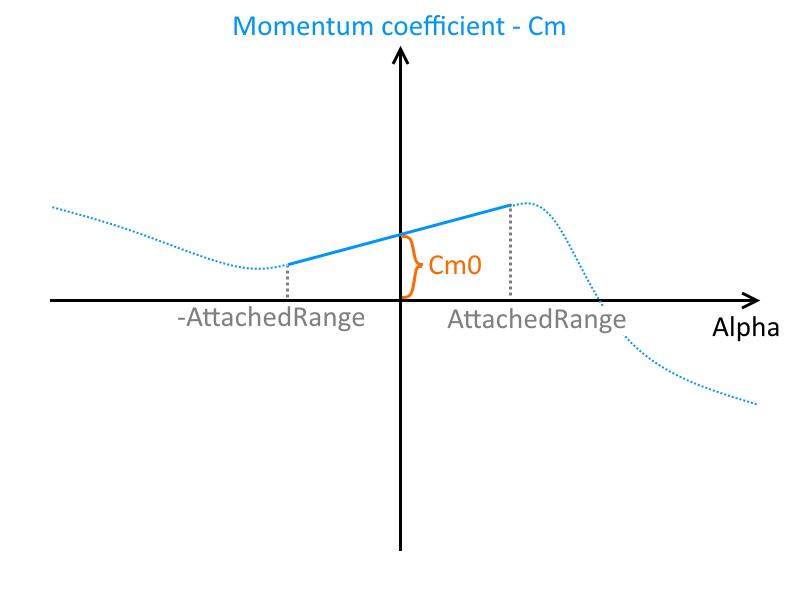
Cm0
Cm0 is the equivalent to Cl0 for the momentum coefficient. It is also zero for symmetrical airfoils. For cambered airfoils this value is usually smaller than zero which creates a pitch up tendency when flying fast (at low angle of attack).
With given geometry, incidence and fixed elevator position theCm0value theCm0attribute directly effects the pitch trim of the aircraft. Increase the value to get a pitch up tendency and decrease it to get a pitch down trim.
An initial value forCm0could be-pi * camber/thickness. For a 3% relative camber that would be about-0.94and for a 2% relative camber the Cm0 starting value could be about-0.63.
Cd0
Cd0 is the drag coefficient at alpha = 0. For a symmetrical airfoil and when Cd0Base = 0 and AttachedCenter = 0 then Cd0 is the lowest drag an airfoil ever produces. To either side of that angle, while in the attached range, the drag grows with a parabolic function.
This attribute determines the drag at high speed (low AOA). It effects the glide ratio.
Values can get as low as0.004for laminar glider airfoils. It is mostly a function of the airfoils thickness and aerodynamically quality. Airfoils for model aircraft have values as high as0.012.
CdAlpha
The drag an airfoil produces due to the effective front area and the beginning of the airflow detachment is modeled with the CdAlpha attribute. This value does not take the induced drag into account because that is modeled entirely with inside the AeroWing class.
Leave theCdAlphaat0.4at the beginning
Cd0Base
The Cd0Base increases the separation drag of the airflow. With higher values the stall produces a lot more drag.
Resulting total drag
The total drag produced by an airfoil in the attached range is calculated with a polynomial function of grade two. (This needs confirmation of the programmer though.)

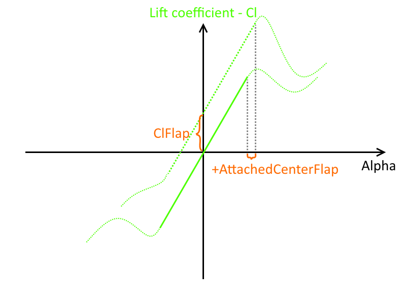
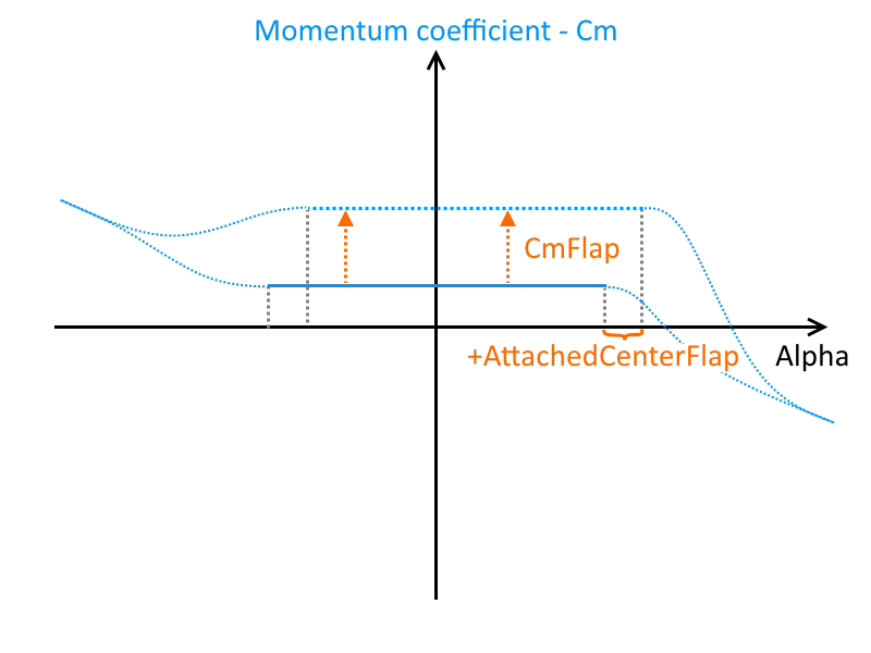
AttachedCenterFlap
The AttachedCenterFlap attribute defines how much the local angle of attack is moved when the flap is deflected. With a negative value the airfoil stalls at a lower angle of attack with a deflected flap than in a clean configuration.
Leave it at-0.12first.
Set a value that is lower to increase the effect of reversed ailerons near stall.
ClFlap
ClFlap represents the increase of the lift coefficient per 1 rad ≈ 57.296° flap deflection. While the default value is 1.5 it is usually a different value in reality. A comparison table for different kinds of flap types can be found later in this section.
2.1is an effective flap and a good value to start with. Use higher values for Fowler flaps and lower values for split flaps.
Increasing this value for the AirfoilTip increases the roll rote of an airplane.
Increase the elevator authority withCmAlpha(see above) and the rudder authority with the AspectRatioMultiplier of an AeroWing.
ReducingClFlapfor the AirfoilTip will reduce the AdverseYaw but also the effectiveness of the ailerons.
CmFlap
CmFlap simulates the amount of pitch up tendency of a flap. A negative value represents a pitch down effect. The value is usually negative. Also refer to the table below for different CmFlap values for different flap types.
Some aircraft need tremendous amount of negativeCmFlap(-0.7or even lower) to maintain level flight when extending the flaps.
Trim the aircraft and extend the flaps while freezing the elevator deflection. Compare the pitch up or pitch down tendency of the real world aircraft to the sim aircraft. Modelling this effect right adds a lot of realism.
TheCmFlapof an AirfoilTip does effect the AdverseYaw.
CdFlap
CdFlap is the increase of the drag coefficient per 1 rad ≈ 57.296° flap deflection. CdFlap must be positive. The default value is 0 which means the flap does not create additional drag other than the induced drag caused by its lift coefficient ClFlap and its deflection angle (AdverseYaw for ailerons). Refer to the table below for some examples.
Real life flaps always create additional drag when deflected.0.005or a little bit higher even is a good value to start with. Some large flaps like double Fowler flaps create more drag and this drag is simulated with a greater value.
Increasing theCdFlapcan reduce the AdverseYaw.
Table of flap coefficients
Recommended values for the Aerofly are:
| Type of flap | ClFlap | CdFlap | CmFlap |
|---|---|---|---|
| Plain flap | 2.1 | 0.0 | -0.2 … -0.5 |
| Split flap | 2.4 | 0.2 | -0.2 … -0.9 |
| Slotted flap | 2.7 | 0.06 | -0.2 |
| Fowler flap | 2.7 … 3.4 | 0.2 | -0.6 … -1.1 |
ClAlphaBase
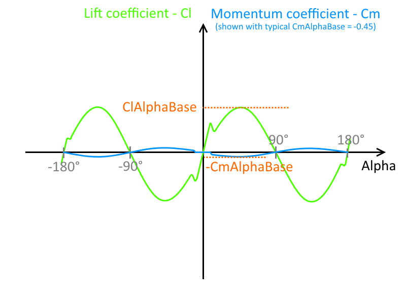
The lift coefficient can be approximated with a sinus function with the wave length of 180° = pi. Only in the AttachedRange and at -180° the airflow significantly deviates.
ClAlphaBase is the amplitude of the sin function and therefor the maximum lift that the airfoil can produce in the stall.
Decrease this value to get a greater wing drop in a stall and during spins. Lower values increase the dynamics of accelerated stalls and maneuvers. Also decrease CdAlphaBase.
CmAlphaBase
Follows the same principle as the ClAlphaBase attribute. Usually this value is negative and the airfoil creates a pitch down force when the angle of attack increases beyond the stall angle (stable). The aircraft will pitch down on its own and accelerate again. A positive value is destabilizing.
ClAlphaBase is usually the maximum momentum coefficient an airfoil will ever create.
The lower the value ofCmAlphaBasethe more the nose will drop when approaching a stall. Values near-0.2tend to soften the stall behavior.
ClFlapBase
The ClFlapBase is the increment in lift coefficient in full stall. It adds to the ClAlphaBase when the flap is deflected.
Use the value to regulate the control surface authority in stall or at a high deflection angle. This increases the roll rate for aerobatic airplanes. (SeeClFlapabove as well)
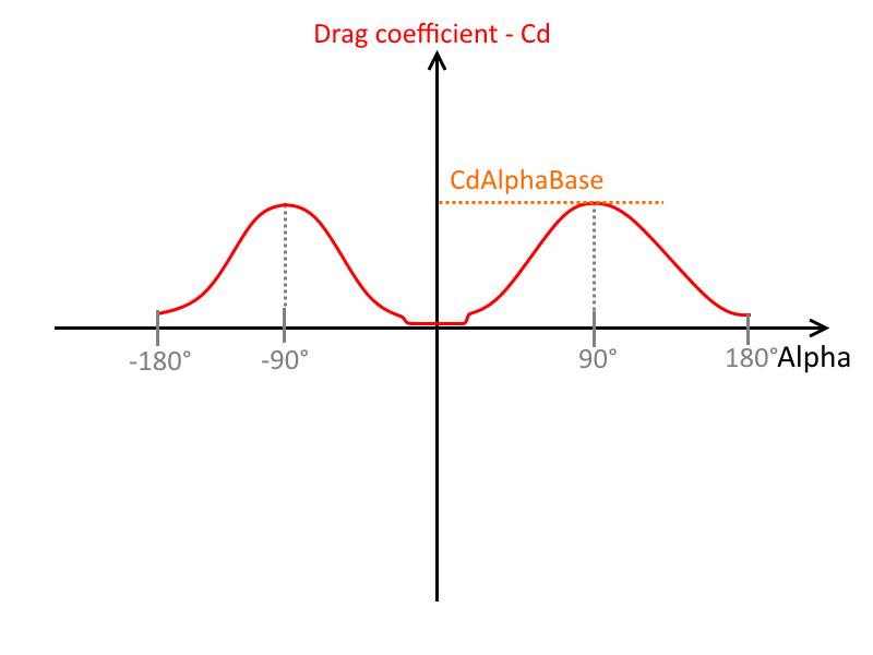
CdAlphaBase
The drag coefficient can be approximated with a sin^2 (sinus squared) function that repeats every 180° = pi. As for the ClAlphaBase the drag of an airfoil only deviates from this approximation when the airflow is attached, which is of course the case inside the AttachedRange but also at -180°. CdAlphaBase is the amplitude of that sin function and therefor the maximum lift that an airfoil can ever create.
Decrease theCdAlphaBaseto lose less energy in accelerated maneuvers and keep the momentum going.
Also modify the AeroFuselageCdyandCdzattributes for fast flat spins.
Example Code
Minimal
This will fall back to default values for all attributes.
            <[airfoil][AirfoilTip][]
            >
All
            <[airfoil][NACA0009][]
                <[float64][Cl0][0.0]>
                <[float64][Cd0][0.007]>
                <[float64][Cm0][0.0]>
                <[float64][ClAlpha][6.28]>
                <[float64][CdAlpha][0.4]>
                <[float64][CmAlpha][0.0]>
                <[float64][ClFlap][2.1]>
                <[float64][CdFlap][0.05]>
                <[float64][CmFlap][-0.3]>
                <[float64][Cd0Base][0.005]>
                <[float64][ClAlphaBase][2.4]>
                <[float64][CdAlphaBase][1.8]>
                <[float64][CmAlphaBase][-0.45]>
                <[float64][AttachedCenter][0.0]>
                <[float64][AttachedRange][0.17]>
                <[float64][StallRange][0.1]>
                <[float64][ClFlapBase][0.5]>
                <[float64][AttachedCenterFlap][-0.12]>
            >