Table of Contents
Scenery Definition File (TSC)
The TSC file is a text file that can be edited with a regular text editor. The file can contain coordinates for an airport, a custom scenery object, runways, helipads and a lot more.
Theses TSC files are placed in subdirectories of “places” folder in the scenery directory. For the creation of new scenery we have to set up a new TSC file and save it in our intermediate scenery folder.
We recomment reading through the Scenery introduction tutorial first
which provices a bit more background.
Let's break down the content of the TSC file.
How to optain the coordinates
Please visit the Geographic Coordinates tutorial to see how you can find out the coordinates that you need for your scenery projects.
Overview
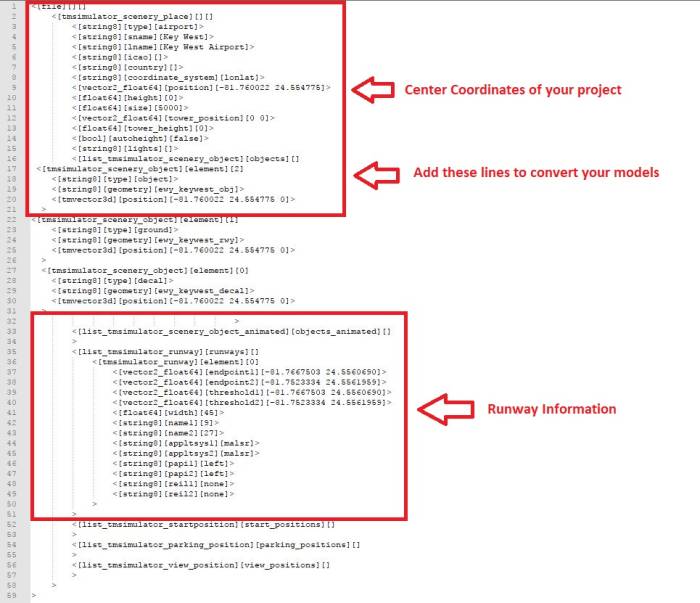
The first area defines the type of scenery object that you defining, e.g. an airport. After that individual scenery objects like the ground mesh or decals are defined. The file then defines runway of an airport, start positions, parking positions and view positions. Entire blocks of the file can be removed when they are not applicable. E.g. you don't need to add the code lines for runways and parking positions if you only want to create a basic scenery object (and not an airport).
Airport/Scenery Parameters
| Parameter | Description |
|---|---|
| sname | = Short Name. This is airport name as shown on the map |
| lname | = Long Name. This a longer version of the airport name when more space is available, e.g. when the airport is selected in the menu. |
| icao | This is the unique airport ICAO code (leave empty if it's not an airport or if the airport doesn't have an ICAO identifier) |
| country | Country in which this scenery is located |
| coordinate_system | Coordinates in this file are defined in this coordinate system. Typically “lonlat”. Some also have “web_mercator” |
| position | These are the center coordinates (lon/lat in decimal degrees) for your project |
| height | Height above ground in meters (usually zero for on ground) |
| size | Radius in meters where the scenery should be visible. Less increases performance significantly. |
| tower_position | Lon/lat coordinates of the airport tower |
| tower_height | Height of the airport tower in meters |
| autoheight | When enabled the airport will be transformed onto the terrain as it's loaded. This allows us to model the airport completely flat and then transform it onto the terrain later. When you set this to false you will have to build your airport at the true height above mean sea level, provide a custom ground mesh and also account for earth curvature, etc. |
Scenery Objects
Individual geometries of the 3D model are used for specific functions such as (generic) objects, ground and decals. These functions are assigned as individual blocks within the tsc file.
You can defined multiple blocks of the same type if needed.
Please also read the documentation of the different object classes.
        <[list_tmsimulator_scenery_object][objects][]
            <[tmsimulator_scenery_object][element][0]
                <[string8][type][ground]>
                <[string8][geometry][keyw_key_west_intl_rwy]>
                <[vector3_float64][position][-81.760022 24.554775 0]>
                <[float64][orientation][0]>
                <[int32][autoheight_override][-1]>
            >
        >
| Parameter | Description |
|---|---|
| type | Type of geometry that is being defined (object, ground, decal, object_transparent_atc) |
| geometry | Name of the object in the 3D model (e.g. ewy_keywest_obj) |
| position | Coordinates (lon/lat) and altitude (in meters) where the object should be placed |
| orientation | Rotates the object above the up axis, angle in degrees |
| autoheight_override | Can force the object above ground |
Animated Objects
Animated objects require an animation to be set before exporting. The exporter then creates a .tma file that contains the keyframe animation data. Both the geometry (.tmb file name) as well as the animation file (.tma file name) are then added to the respective lines in the objects_animated elements.
        <[list_tmsimulator_scenery_object_animated][objects_animated][]
            <[tmsimulator_scenery_object_animated][element][0]
                <[string8][geometry][animations_guy_talking]>
                <[string8][animation][animations_guy_talking]>
                <[vector3_float64][position][11.350648 47.257897 0]>
                <[float64][rot_in_degree][0]>
                <[float64][duration][0]>
                <[float64][time_scale][1]>
                <[bool][autoheight][true]>
            >
        >
| Parameter | Description |
|---|---|
| geometry | File name of the geometry |
| animation | File name of the animation |
| position | Lon/lat coordinates and altitude in meters of the geometry origin (without animations applied) |
| rot_in_degree | Rotation of the object around the up direction (without animations applied) |
| duration | Duration of the animation sequence, zero for auto |
| time_scale | Timelapse factor 1 = real time, 2 = twice the speed, 0.5 = half the speed |
| autoheight | places object onto the terrain when loaded. When false then the altitude has to be set to meters above mean sea level |
Runways
Each runway is defined in the tsc as a set of coordinates (lon/lat).
Example section:
            <[tmsimulator_runway][element][0]
                <[vector2_float64][endpoint1][-122.396054939917 37.6298574167513]>
                <[vector2_float64][endpoint2][-122.356142019883 37.6131189526278]>
                <[vector2_float64][threshold1][-122.393396225665 37.6287425367392]>
                <[vector2_float64][threshold2][-122.357143317297 37.6135389173978]>
                <[float64][width][60]>
                <[string8][name1][10L]>
                <[string8][name2][28R]>
                <[string8][appltsys1][malsr]>
                <[string8][appltsys2][alsf-2]>
                <[string8][papi1][left]>
                <[string8][papi2][left]>
                <[bool][papi1_has_custom_position][false]>
                <[bool][papi2_has_custom_position][false]>
                <[vector2_float64][papi1_custom_position][0 0]>
                <[vector2_float64][papi2_custom_position][0 0]>
                <[float64][papi1_glide_slope][3]>
                <[float64][papi2_glide_slope][3]>
                <[float64][papi1_spacing][6]>
                <[float64][papi2_spacing][6]>
                <[string8][reil1][none]>
                <[string8][reil2][none]>
            >
| Parameter | Description |
|---|---|
| endpoint1 / …2 | Lon/lat coordinates of the end of the paved part of the runway in the first and second direction |
| threshold1 / …2 | Lon/lat coordinates of the runway threshold for the first and second direction |
| width | This is the width of your runway in meters |
| name1 / …2 | Runway identifier for the first and second direction |
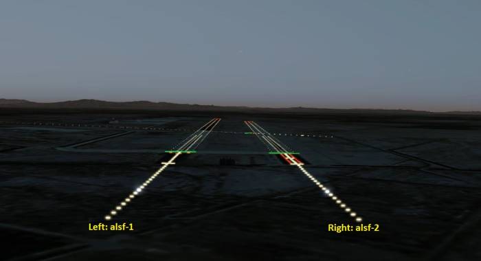
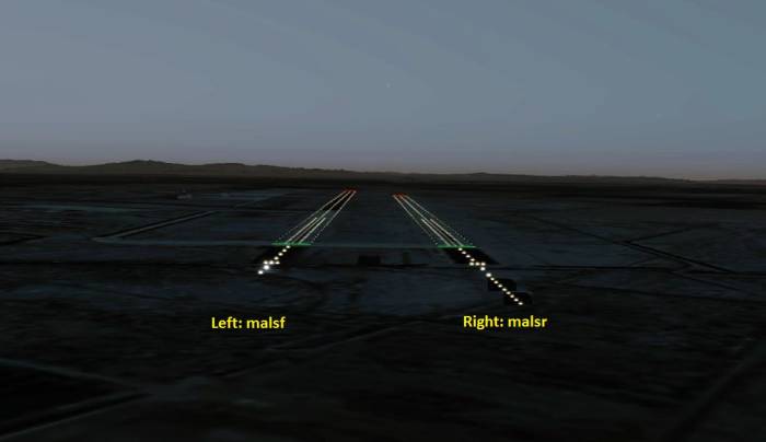
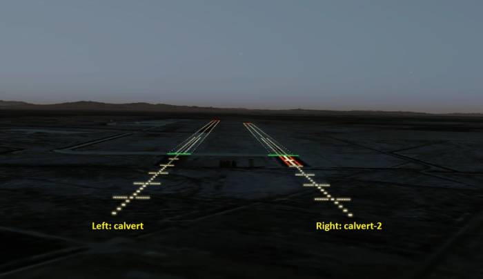
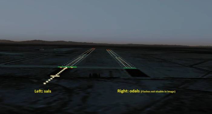
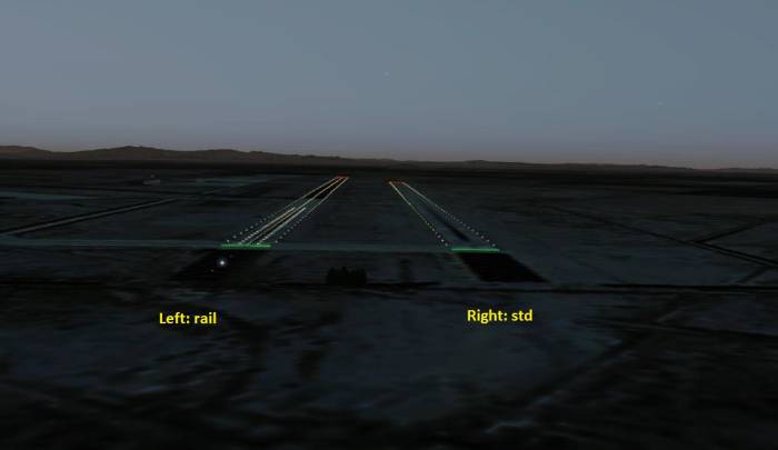
| appltsys1 / …2 | Approach light system installed for the first and second approach end |
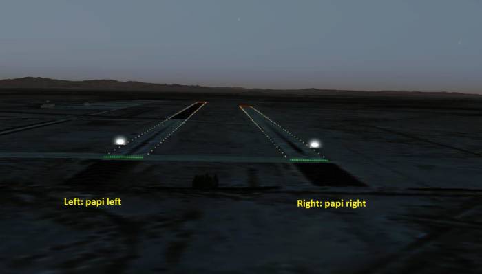
| papi1 / …2 | This side of the of the precision approach path indicators (PAPI) |
| papi1_glide_slope | Glide slope angle of the PAPI lights in degrees |
| papi1_custom_position | Manual offset of the PAPI lights in meters |
| papi1_spacing | Distance between individual PAPI lights in meters |
| reil1 / …2 | Runway end identifier lights (REIL) |
Approach Lighting System (ALS)
appltsys1 - approach lighting system on approach end 1
appltsys2 - approach lighting system on approach end 2
| Value | Result |
|---|---|
| alsf-1 | Approach Lighting System with Sequenced Flashing Lights configuration 1 |
| alsf-2 | Approach Lighting System with Sequenced Flashing Lights configuration 2 |
| malsf | Medium-intensity Approach Lighting System with Sequenced Flashing lights |
| malsr | Medium-intensity Approach Lighting System with Runway Alignment Indicator Lights |
| sals | Short Approach Lighting System |
| odals | Omnidirectional Approach Lighting System |
| calvert | High Intensity Approach Lighting System ICAO-compliant configuration 1 |
| calvert-2 | High Intensity Approach Lighting System ICAO-compliant configuration 2 |
| rail | Runway Alignment Indicator Lights |
| std | Standard runway lighting |
| none | no approach lighting system |
Precision Approach Path Indicator (PAPI)
papi1 - precision approach path indicator on approach end 1
papi2 - precision approach path indicator on approach end 2
| Value | Result |
|---|---|
| left | papi position left of runway when approaching |
| right | papi position right of runway when approaching |
Runway End Identifier Lights (REIL)
reil1 - runway end identifier lights as seen from approach end 1
reil2 - runway end identifier lights as seen from approach end 2
| Value | Result |
|---|---|
| reil_uni | reil in one direction |
| reil_omni | reil in all directions |
Helipads
Helipads are defined in the tsc file as well:
Example:
        <[list_tmsimulator_helipad][helipads][]
            <[tmsimulator_helipad][element][0]
                <[string8][name][H1]>
                <[string8][type_name][building]>
                <[vector2_float64][position][-81.7599657782887 24.5549091932849]>
                <[float64][radius][8]>
                <[float64][heading][89.13]>
                <[float64][height][0]>
            >
        >
| Parameter | Description |
|---|---|
| name | Name of the helipad |
| type_name | Name of the helipad type (e.g. building) |
| position | Lon/lat coordinates of the helipad |
| radius | Maximum rotor radius in meters |
| heading | Direction of the parking position in degrees from true North |
| height | Height above ground in meters |
Parking Positions
Towards the end of the file you can define individual parking positions.
Example:
        <[list_tmsimulator_parking_position][parking_positions][]
            <[tmsimulator_parking_position][element][0]
                <[vector2_float64][position][-122.387688269125 37.6102106074827]>
                <[float64][heading][29.28]>
                <[string8][name][Parking Position #1]>
            >
            <[tmsimulator_parking_position][element][1]
                <[vector2_float64][position][-122.378445704023 37.6277080224156]>
                <[float64][heading][297.68]>
                <[string8][name][Parking Position #2]>
            >
        >
| Parameter | Description |
|---|---|
| position | Lon/lat coordinates of the parking position |
| heading | Direction of the parking position in degrees from true North |
| name | Name of the parking position (e.g. West or East apron, etc.) |

