Table of Contents
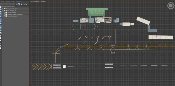
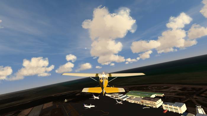
Building an airport in 3DS Max; Key West Style
Introduction
In this tutorial I will show you how to build an airport in 3DS Max step by step using the complete Florida Keys scenery as a reference. The entire process seems overwhelming but once you get an understanding of the format it's much simpler than it appears to be. I will cover the following stages in this tutorial to ultimately build an entire airport:
- obtaining your reference image and aligning it to real-world coordinates
- building the objects for your airport and placing them onto the reference image
- making the groundpoly (smooth surface) that your objects will sit on
- adding your decals and finishing touches to your airport
- exporting the required sections from Max into your project folder
- converting your airport to be used in Aerofly FS
Note: there are many different variations of this process that will indeed work but all variations will still follow the same concept as shown within this tutorial.
Let's get started:
3DS Max Setup
In order to build your airport correctly you will need to set up 3DS Max properly. There are only a couple of items required for this to insure you obtain the best results with your project.
View
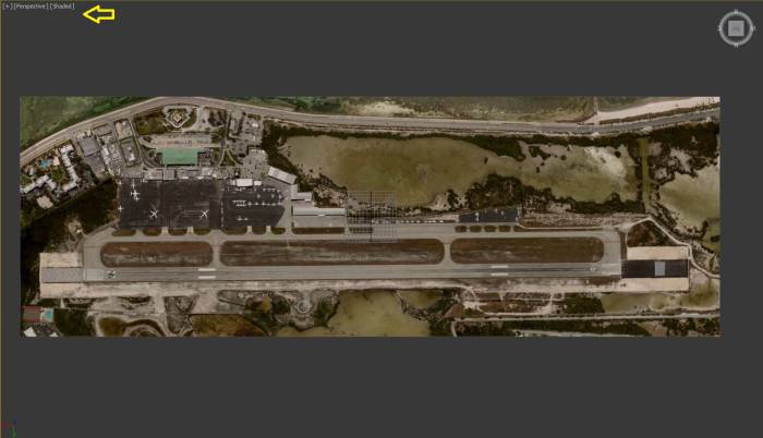
For best results you should set your viewport to one screen with perspective and shaded selected
Resolution
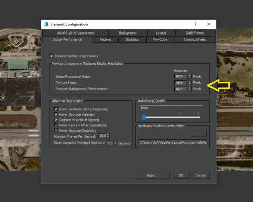
The resolution is important to the placement of your models and decals. Let's set this setting by clicking on the little '+' in your viewport and select 'viewport configuration/display performance'. You want to change the 'texture maps' number to 4096. This will give you a good reference image to work off of.
Coordinates
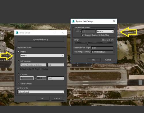
And the most important setting is to set your coordinate system within 3DS Max to match hat's needed for the conversion into Aerofly. From within 'customize/unit setup' the display unit scale should be set to metric/meters and set the system unit setup to 1 unit-I meter
Project Reference Image
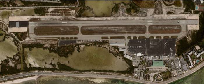
The reference image will be used as a guide for your entire airport project. This image will not ever be exported from 3DS Max as it's solely a guide to line everything up. This is very important to set up properly otherwise your entire airport will not line up to the real-world coordinates used in Aerofly.
Note: prior to making your airport(s) it's assumed that you have already made the geoconvert scenery for that area. This tutorial will also assume this step has been completed.
Here are the steps necessary to make this:
- Go into FSET and rubberband an area only around the airport that you wish to make
Note: Make this image as high resolution as you can as it will be used for the reference image in 3DS Max; I made the image with (-1) FSET resolution.
Note: Make sure this only produces one image file
- From the FSET main screen, make note of the coordinate for center and the nautical miles noted for the image area.
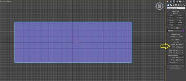
- Now take the nautical miles noted on the FSET screen and convert them to meters, these will be used for the length/width of the panel that you need to make for the reference image. In this example the nautical miles (nm) noted on FSET are: 1.028 x 0.352, these get converted to: 1903.856 x 651.904 meters
- Begin your project by selecting the object plain and editing the meters to match the resulting meters converted by the FSET image
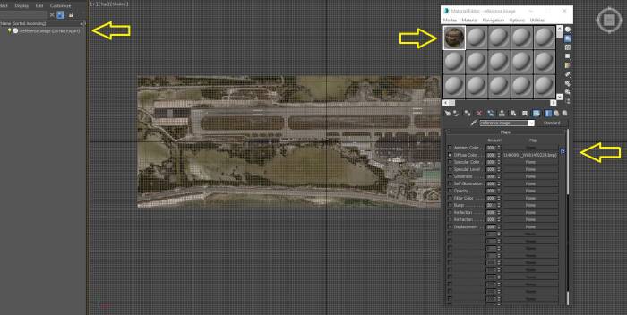
- Add the texture (FSET image file) to the plain by mapping using the material editor.
- Rename the plain to 'reference image (Do Not Export)' The reference image will never be selected for export and it will only be used to position your objects.
Now might be a good time to save your project. As a rule of thumb you should always create save points throughout your progress. If you mess something up, you can always go back to your last save point, so you can never have too many saves with different save names for example: 1-reference image, 2- began modelling, 3- made terminal, etc.
Model Creation
Now that we have a good reference image for our project and we know that it's aligned properly to the real-world/Aerofly coordinates we can begin to make our airport model (hangars, terminals, tower, etc.). Have fun with this step as the more detail that you add to your models, the more realistic your airport will be. In this tutorial we will keep things rather simple to move things along.
Note: You can either make your own models or import them in if you already have them. IPACS will also be publishing a model library that you will also be able to use for this step.
In this tutorial section I will show you how to make and texture a basic object, how to create lit objects that will light up at night in Aerofly, and how to export the object group and set up your tsc file for the model conversion.
- Lets begin by taking a look at your reference image and identifying which models you want to make for your airport. In the Key West International Airport you can see that we have a FedEx center, a customs center, the main terminal, a fire station, a parking garage, and some hangars to make.
Note: Gather as many photos as you can for both reference to build your models and to use for texturing later on. In this tutorial I'll show you how to build and texture the FedEx Center. Since most models are made practically the same, I'll leave the rest up to you.
- For the modeling part it's best to change your viewpoint to two screens; a top and perspective. This will allow for you to line up your model as well as see it from all different directions in 3D as it will be seen in Aerofly later.
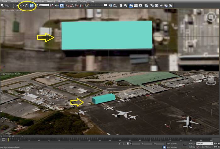
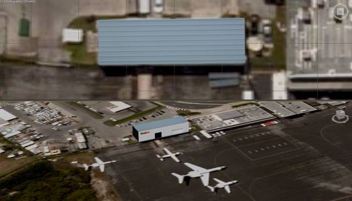
- For the FedEx Center, lets choose a box object. Place it using the top viewpoint for easier positioning. Looking at the photos that you gathered, judge the height for now (you can always adjust the height later once you test in Aerofly)
- Line up the box by using your editing tools to fit directly in place
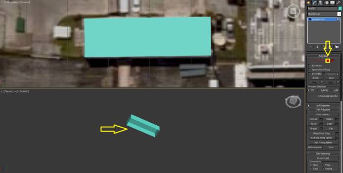
- Next, change the box to an 'editable poly' so that you can edit and add textured to your new FedEx Center
Note: In order to keep polygon counts down and keep Aerofly performance up always try to eliminate any sides that aren't visible once you convert your models.
- Lets select polygon so that you can highlight each side of your box. Highlight the bottom side of the box and delete it
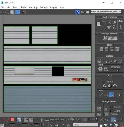
- Next add the modifier: Unwrap UVW, Click on polygon icon again plus the 'select-by-element' box to the right of the polygon button and click on the Open UV Editor button to open up your box texture layout.
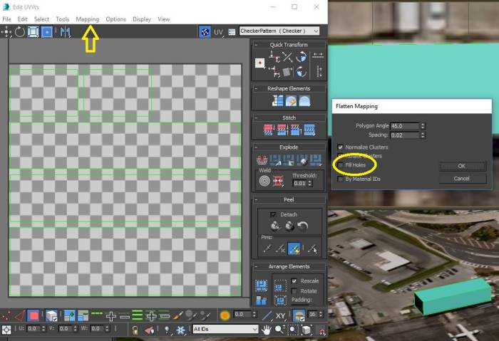
- With the UV editor opened I usually use the flatten mapping selection under the 'mapping' tab in the editor window. There are many different ways to arrange your model for texturing that you can use but for this tutorial i'll show you this way as it arranges the elements nicely.
Note: For easier placement make sure that you uncheck 'fill holes'
Exporting to Gimp
In this tutorial I'm going to show you how to add textures to your model using Gimp. This way you can see some special techniques used to set up your textures. You can use any photo program for this but Gimp is powerful and free to use.
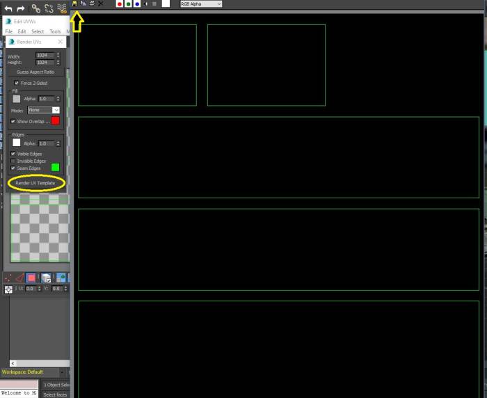
- From the 'Edit UVWs' box, from tools choose Render UVW Template, leave the default settings and click 'render UV template'
- Click on the save icon and save the image rendered as a JPG and lets name the image 'fedexcenter_color' to whatever location you prefer.
Note: it's important to include the suffix _color for each of your map images. You should follow this requirement for each model that you create.
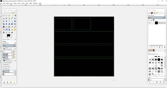
This is the image that you are going to edit in Gimp with your own textures
- Open the image in Gimp
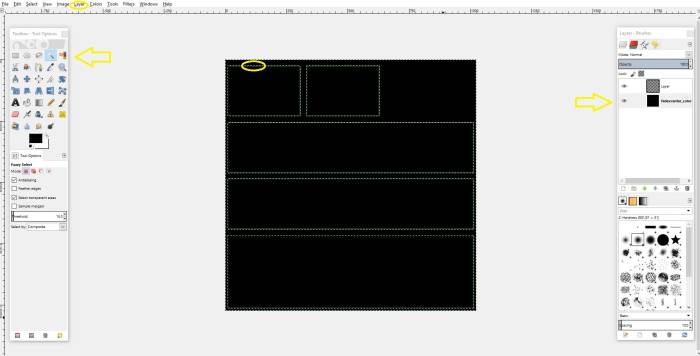
- First we need to add a layer
- On the right in the layers editor, highlight the image again and select the fuzzy select tool and click anywhere in the outer part of the black area on your image. You will see your outlines begin to wiggle
- With the boxes wiggling, right click/copy - then select the new layer that you created - right click/paste
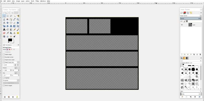
- Select the 'rectangle select tool' and click on anywhere on your image. You will now see that the new layer that you created now shows the boxes but with checkboard (transparent) sections.
- Select the 'fedexcenter_color' layer and right click/ delete layer. Here's the result:
Now that we've set up the image map for adding textures lets get that FedEx Center textured in our project.
In Gimp, you can now add layers and move images onto your map.
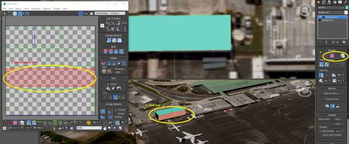
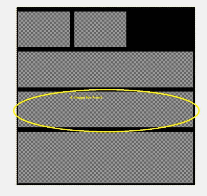
In looking at your map image in Gimp, you can reference the map in 3DS Max to see which sides on your model are where on the image map simply by clicking on your model in Max.
Note: The image box seen on the map image is upside down, so when you add your texture to that box be sure to flip it.
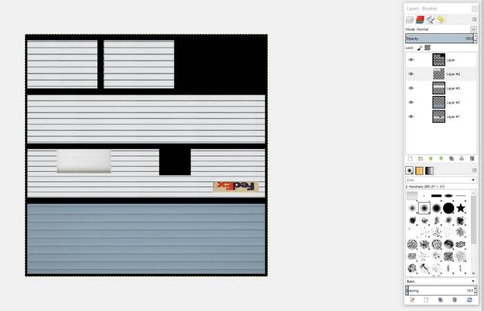
- Using layers and the image tools in Gimp place all of your images onto your map to your liking. The result should look something like this:
- Finally we want to export as the completely textured image map. If you followed the tutorial you will see that 'fedexcenter_color.jpg' is already there for you. Just select image as JPEG and replace the original map image.
Close out Gimp and go back into 3DS Max. In the upper right corner of the Edit UVWs window you will see a box with 'Checker Pattern (Checker)' inside it. Replace it by selecting 'pick texture/bitmap'. Locate the map image that you just created and select it in place of the checker image.
- Now close the edit window and open the material editor
- Choose an empty ball, click on the '+' on Maps
- Click on 'none' on the Diffuse line/bitmap, and choose your mapped image 'fedexcenter_color'
- Drag the ball onto your model in the viewpoint
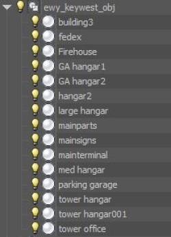
- Rename your box to something that references the object you created. In this tutorial I will name it 'fedex'.
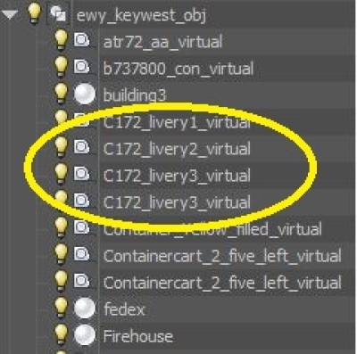
- This model (fedex) along with all of the other models that you create for your airport must be grouped into a folder called xx_obj. In this tutorial we will call it: ewy_keywest_obj
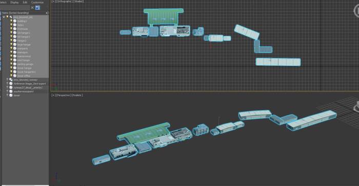
Note: As you can see in the image below, all of the models are built, textured, and grouped in the proper format.
As you can see, your first airport building is modeled and textured. There are many things that you can do to make a nice scenery model, this only showed you a very basic building process. In the completed 'Florida Keys' scenery package you will see that the FedEx building has an inside as well, this is possible when you model as well.
Exporting Object Group and Airport TSC File Object Entry
Prior to beginning this section be sure that the latest 3DS Max IPACS plugin is placed into the 3DS Max/plugins folder.
In this section we will learn how to get your models to show up in Aerofly successfully.
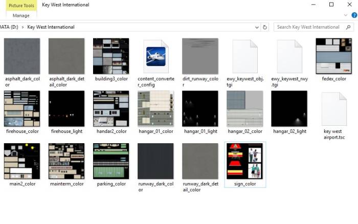
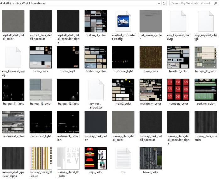
This is a good time to create a project folder for your airport. This folder will have everything needed to run the converter and make your airport in Aerofly. For this tutorial we will make a folder named: 'Key West International“. Inside the folder will include:
- the 'content_converter_config.tmc' file; This is the main file that you use to run the converter for your airport.
- all of your exported TGI files; these files are the result of exporting portions of your airport from 3DS Max.
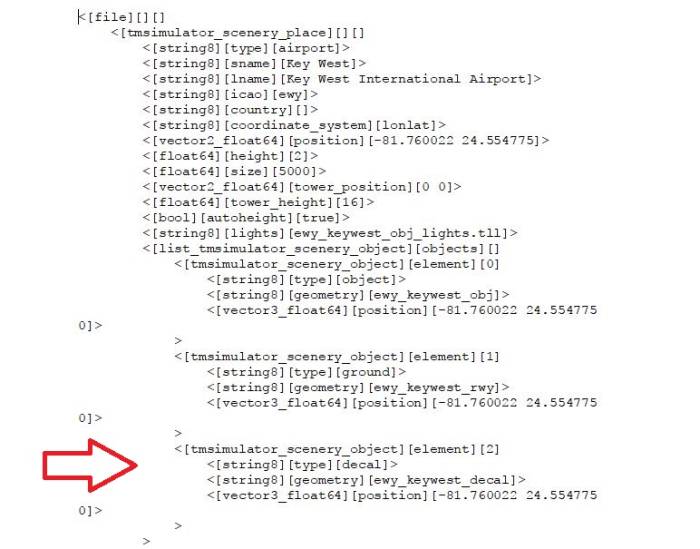
- the TSC file; this is your root file for your airport. This file will have all of the coordinates and information for your groups in it. Configuring this file is simple but very important to get correct. We will go through each part in this tutorial for a better understanding.
- all of your texture files; these files will have the suffix XX_color. Make sure that you place every texture file that you create for your models into the project folder. Failure to do so will draw an error when converting your airport.
- all lightmap files; we will learn how to make these further on in the tutorial. The lightmap files have the suffix XX_light. These files are very much like the XX_color files. These files will allow for you to see lights in your models or objects inside Aerofly.
Let's begin this section by exporting your model group.
- From within 3DS Max select and highlight all models that you have created and added to the XX_obj group. It would also be smart to in-light all of the other bulbs in your project listing.
- Choose Export Selected from the main menu
- pick the destination folder as your project folder that you just created, choose IPACS TGI/TSC Exporter from the 'save as type' drop down, and name your file ewy_keywest_obj and click on SAVE.
This will make your TGI file for your airport models.
- Next, move all of your xx_color files that you made for your models into your project folder.
TSC File Explained
Once you have your TSC created to your needs go ahead and add it to your project folder. The section directly related to your models is shown in the image below.
Note: If you wanted to convert only your models at this point you can do so however you will need to omit the lines for groundpoly and decals in your TSC.
Let's recap what we have completed so far:
- Models were created and exported as a group (TGI) to your project folder
- All image map folders used in making your models were added to the project folder
- Your TSC file was created and added to your project folder
Creating your Groundpoly
In this section of the tutorial we will learn how to add the groundpoly to your project. This is an important step for your project as it will both define the ground cover that you wish to texture, and which ground cover you wish to keep transparent showing only the imagery below. The groundpoly will also smooth and flatten your airport and remove the bumps of your runway.
Lets begin.
- For your work on the groundpoly it's best to change your viewpoint in 3DS Max to show only the top down view and add have 'edged faces' selected.
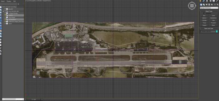
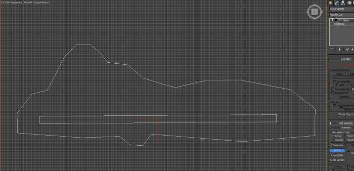
- Using a line (shapes) make an island around your reference image, and be sure to close the spline
- Using the rectangle, make a box around your runway, adjust as necessary until if aligns perfectly. Use your zoom function and use tools necessary to get this as close as you can to the runway shown on your reference image.
Note: In this tutorial we will show you how to add your runway texture only, if you wish to texture the apron area be sure to carve that area out as well. The steps needed to add the apron will be the same only adding a separate material ID for it.
- at this point you can go ahead and hide the reference image from view as it won't be needed anymore.
- With rectangle selected, add modifier- edit spline and attach rectangle to line
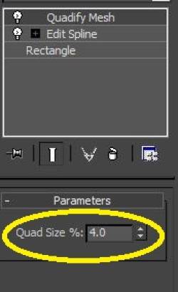
- While highlighted, add modifier – quanify mesh. You will see that the area around the runway has been filled in and cut into sections. Take a look at the way the cuts are positioned; you don't want the cuts jammed up together so you may need to adjust the spacing to get the cuts more evenly placed.
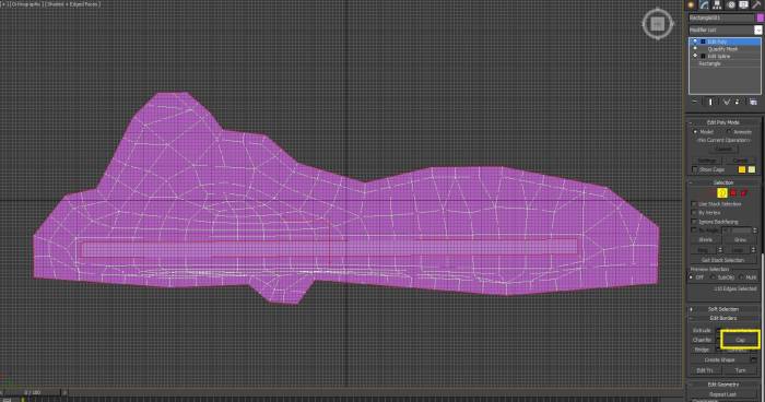
- add the modifier - edit poly
- Highlight the runway border and click cap (this fills the hole for the runway as seen in the photo below)
- With the border around the runway still highlighted, click the chamfer edit box to the right of chamfer edit. Make the chamfer 1m and click check box in edit window box that comes up.
Now, as you can see that the runway is a solid plain. Since Aerofly works better with sectioned material you need to add some cuts to the runway.
- Add cuts to runway from outer edge to outer edge on opposite side (edge made by chamfer). Place some cuts all the way down the runway plain.
Note: Clicking the right mouse button completes each cut.
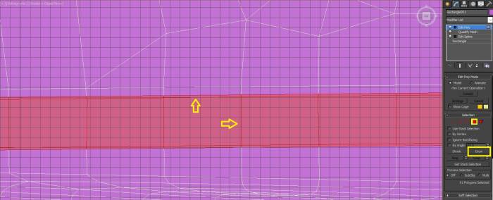
- Select the polygon of runway (in right menu) and click on grow. Notice the grow function extends the runway over the chamfer edge just created.
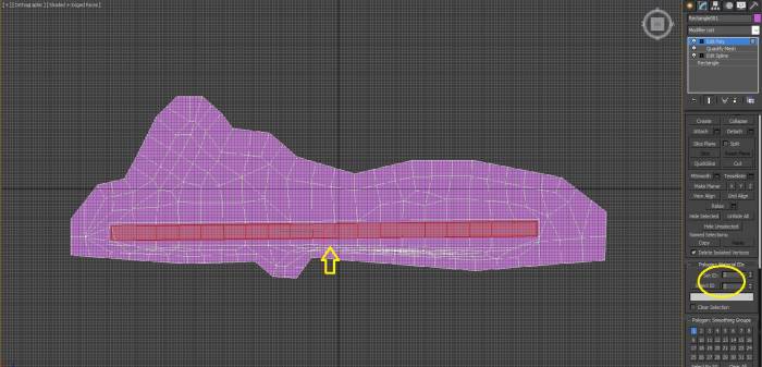
- With runway polygon (and chamfer extension) selected, set the polygon material ID to 2. This will create a unique ID for the runway which will be needed once we add our texture to it.
Texturing Groundpoly
Now that we have completed the basic template for the groundpoly it's time now to texture it.
- Open your material editor
- Select an empty material ball (you will need three balls as described in this tutorial, more will be needed if you have other sections such as apron)
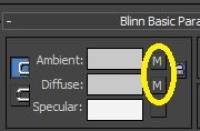
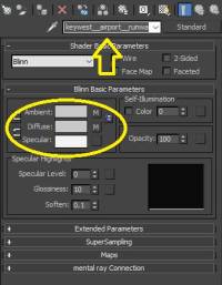
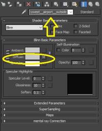
- You will need to add a texture for diffuse and ambient. The diffuse texture should be the texture that you want for your base runway texture, and ambient will be the layer on top such as tire marks or dirt. Also for ambient channel make sure that you change the material ID to 2
Note: For premade textures you can use the textures in the Kingman Demo. For all texture files, they will need to have the suffix _color and needs to be placed in your project folder as described earlier.
Note: When adding textures always remember to go back a level in the drop down next to 'standard' to insure you are in the correct group.
- Once you add the texture files for both diffuse and ambient, go back to default and rename it to xx(underscore underscore)airport(underscore underscore)runway (note the two underscores). In this tutorial it will be named keywest(underscore underscore)airport(underscore underscore)runway. This will be the material ball reserved for the runway.
- Now select a second material ball and add a texture to diffuse in the same fashion as the previous ball. This doesn't matter too much as this won't be seen in Aerofly at all but it still must be defined. Go back a level to default and rename this one to xx(underscore underscore)airport(underscore underscore)outside (note the two underscores). In this tutorial it will be named keywest(underscore underscore)airport(underscore underscore)outside.
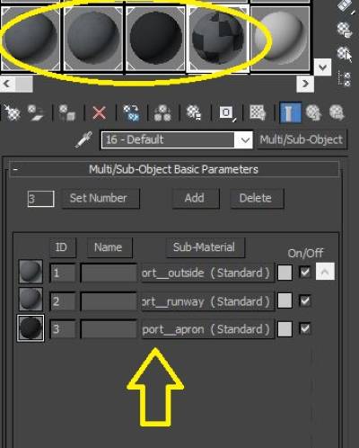
Now we want to create a third ball that will be used to combine the runway and outside textures into one texture group.
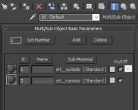
- Select a third ball and click on the standard button. Change it to multi/sub object
- Drag and drop the ball that you created for outside into the line for ID 1
- Drag and drop the ball that you created for runway into the line for ID 2
- Reduce the 'set number' to 2 since that's all that we are using here. If you have created more areas you just drag and drop them into the corresponding ID's
The result will look like this:
- Finally, drag the multiball onto your groundpoly model.
Vertex Coloring
Now, with your textures set and bound to your groundpoly now it's time to add the vertex coloring. The vertex coloring is where you define what gets seen in Aerofly and what doesn't.
Let's begin:
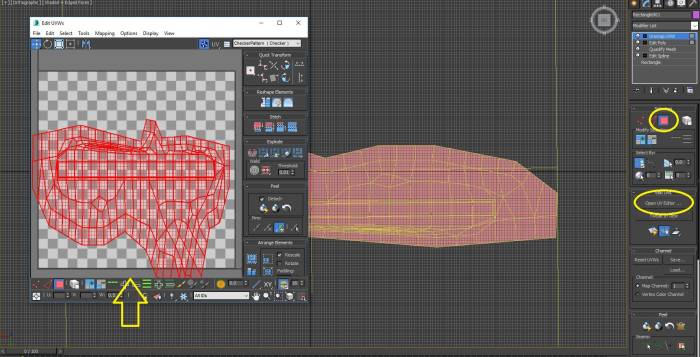
- Highlight the entire groundpoly (press CTRL-A to ensure this if needed), and add modifier - UnwrapUVW
- Select the polygon button on right and Open UV Editor
- From within the UVs Editor window, zoom out to see more of the area then stretch out the groundpoly so that it's more uniform
- add modifier - edit mesh while groundpoly is selected
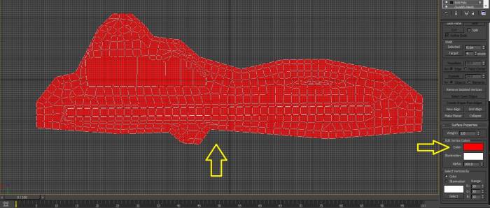
- Click on the vertex button on right menu; add vertex dots on model should now be highlighted red. If not press CTRL-A.
- Go to bottom of the menu and click on the white box after color in the edit vertex colors, change this color to full RED (255,0,0)
Now we need to select the outside vertex only (with the runway vertex unselected)
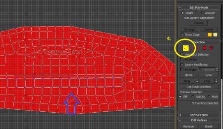
- 1. Add the modifier - edit poly, 2. place a check in the clear selection box, 3. select ID 1, 4. click polygon button on top of menu and while holding the CTRL key select vertices selection.
You will now notice that all of the vertices are selected as red except for the runway.
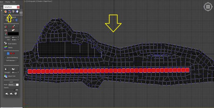
- Add modifier - edit mesh, make sure that vertices are selected and go to bottom of menu and click on box after color in edit vertex colors, change from red to full black (0,0,0)
- add the modifier - vertexpaint and click on second button (vertex color display) to see the colors
You should see everything colored black except for the runway now.
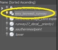
- Rename the groundpoly group to XX_runway
- Select only that group (as explained before) and export selected as a scenery place (when the box appears) and named XX_rwy. In the tutorial we will export it as: ewy_keywest_rwy into your project folder.
Now that we have completed out groundpoly it's safe to add the lines for it to our TSC file:
Note: If you wish to add an apron texture to your airport, you should add that area the same way you did for the runway however, you will need to assign a different material ID to that area. in a new material ball add the apron colors and save the texture name as xx(underscore underscore)airport(underscore underscore)apron. Add to same multiball used for runway and outside.
Tutorial Recap
OK, looking at the progress, you should have now completed the following:
- Models were created and exported as a group (TGI) to your project folder
- All image map folders used in making your models were added to the project folder
- Your TSC file was created and added to your project folder
- Your groundpoly was created and exported into your project file
- You added the lines for your groundpoly into your TSC file.
Taking a look at your project folder, it should now look something like this:
Adding Decals
Now that you have built your airport groundpoly and objects it's now time for the final core step. The decals are the detailed lines and markings that go on top of your runways, apron, and taxiways.
Let's begin.
To best prepare for adding your first decals you should perform the following steps:
- Change your viewport by going into the viewport configuration and setting your view to one window set to top so that you can have a large top down view. This is the best view since all decals sit flat onto your surface.
- It's best to hide everything in your hierarchy except for your reference image. This will make it easy to place your markings without obstruction.
Once you have your workspace configured for decal placement let's move on to adding our decals.
There are many different techniques to make decals, in this tutorial we will learn a few different common approaches.
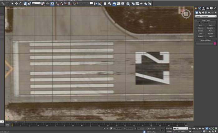
Let's begin with some simple runway markings:
- Zoom in to get a good view of the area you are working on.
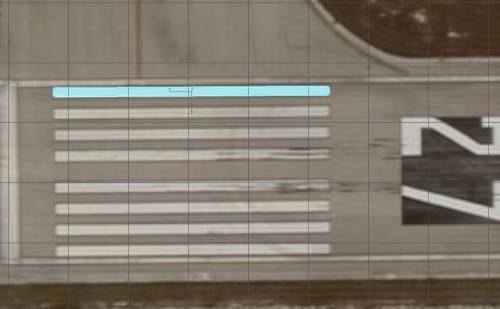
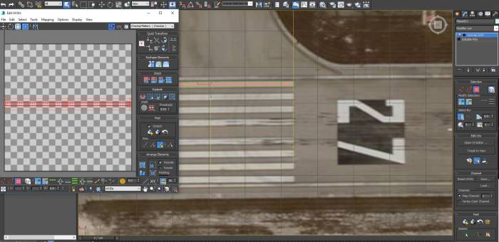
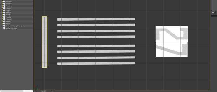
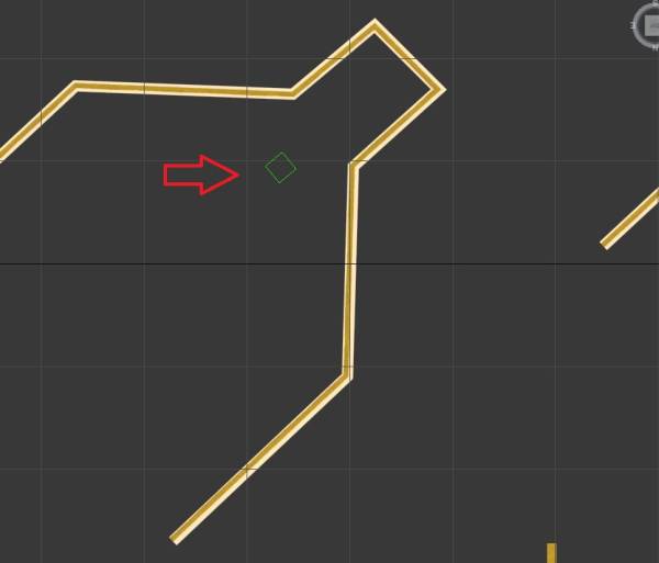
- Select the plane object and place it precisely over one of the parallel lines on the reference image
- Convert the new plane to editable poly by right clicking the plane and selecting convert.
- Adjust the plane as necessary so that it's perfectly over the image line.
Next let's add our texture. Note by adding a texture to our new plane now allows for you to make copies of your plane quickly if more than one is needed.
- With the plane still highlighted add the modifier Unwrap UVW
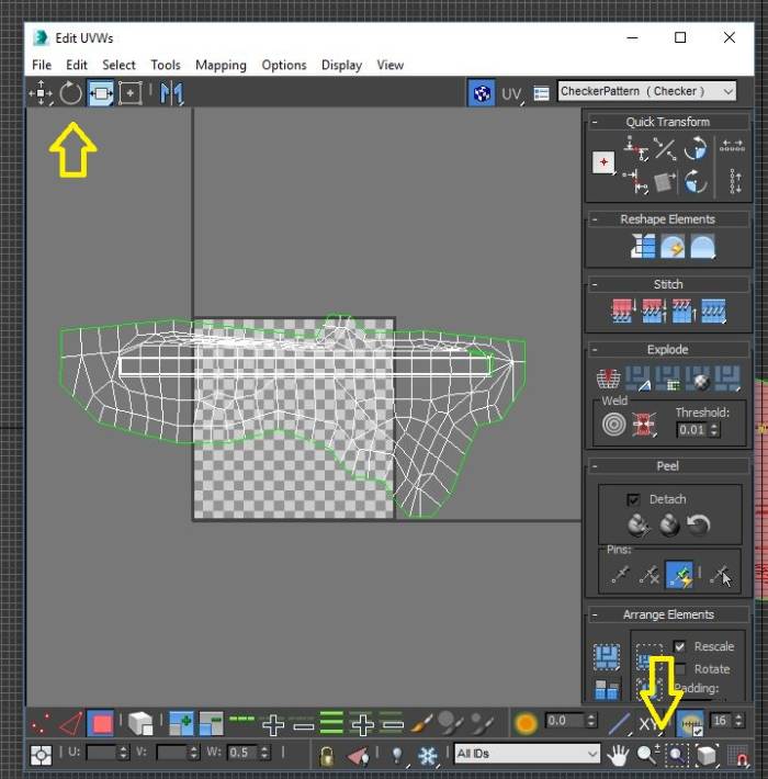
- Select polygon with the 'select by element' toggle checked. Make sure that your plane is highlighted fully red. If not click back on the plane.
- Open UV Editor and click on the mapping tab and select flatten mapping. Make sure that you uncheck the fill holes box.
Next we add our texture.
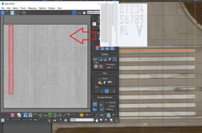
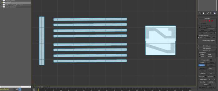
- Replace your checker pattern by selecting your new texture for your first line (drop down/pick a texture/bitmap)
- With the new texture in the box manipulate your line to fit over the texture that you need. Note in my example the texture is very difficult to see due the transparency.
- Add the map to a free material ball and drag the ball to your plane
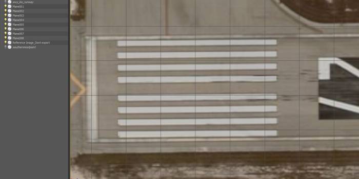
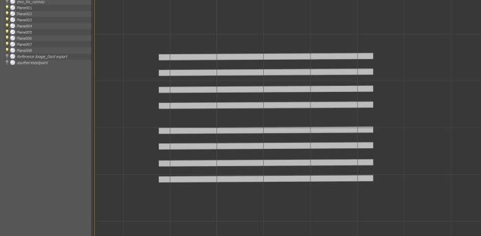
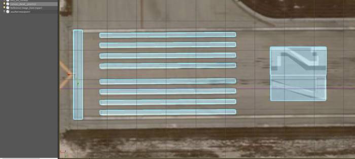
Now that we have the texture added to our plane we want to make some copies to finish the remaining lines. Note in this situation it's faster to copy the first four then highlight those four and copy the group to finish the other four. Use clone/instance to make your copies.
Here's your result:
Let's now continue by making more common lines in the same way. For any lines that are straight they can all be made with a simple plane object, even the runway numbers.
Once you have all of your decal objects made be mindful that you can set priorities of your decal groupings. These priorities allow you to overlap decals over other decals. priorities can range from 0-9, with 0 being the bottom most decal.
OK, let's assume that you have made enough decals that you want to start grouping them. Note you can group as many decals together as you wish.
Let's now take the decals that we made in the tutorial and group them properly.
- Select one of the planes that you made and convert it back to an editable poly, and click on the attach function from the right menu group.
- One at a time click on each of the decals that you want to group together.
- Next lets rename the plane that now contains the group of attached planes. Please pay attention to the naming of this as it must have two underscores before the priority delegation. Let's name this runway_decal(underscore underscore)priority0
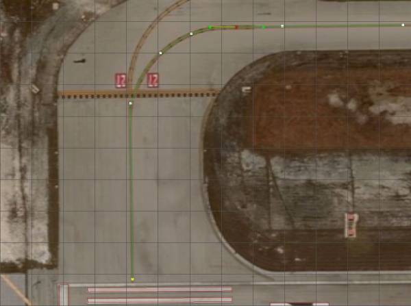
Let's now continue making our decals using a different method. As many taxiways have straight taxiway centerlines with curves as well, it would be very difficult to make these with just a plane object. Let's try this now by using the line object.
- Click on the shapes button and select line. We are going to use the “bezer” function so let's click on that under drag type.
- By using this function pick your starting point and click. You will see the line form while you move your mouse. To make your curve you need to press and hold your mouse button while moving. This takes some time to perfect so you may need to practice a bit.
Once you are finished with your line you need to right click to cut the line off. note you can make adjustments to your line by clicking on the vertex dots and moving them around.
- Make a second line roughly the width of the line that you are making. This line will be used to define the taxiway centerline width.
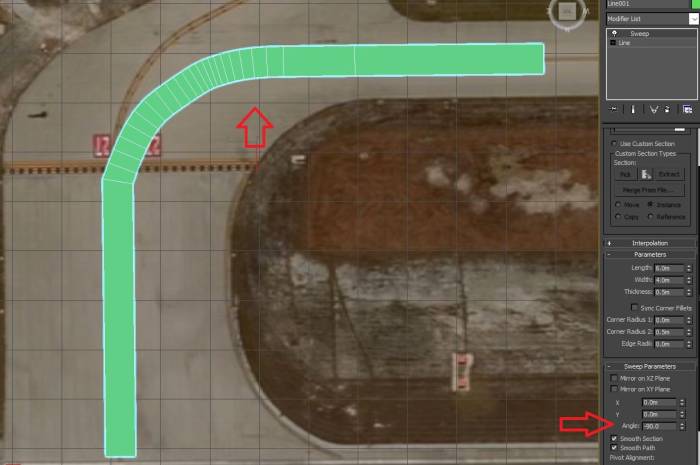
- Highlight the actual line defining the taxiway line and add the modifier sweep
- In the sweep parameters find angle and type -90. You will now see the line change to a wide plane.
Now, we need to change the width of that wide line to match the actual centerline of the taxiway.
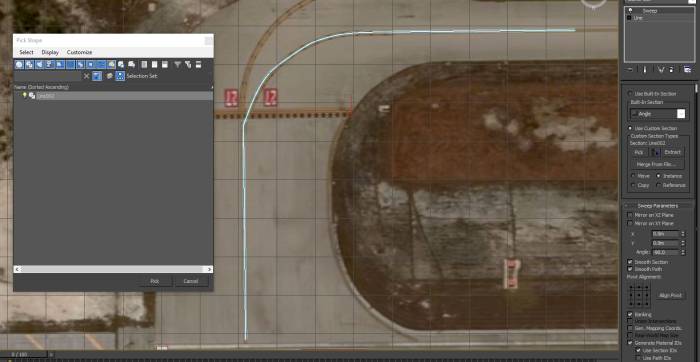
- Under the box with “angle” in it select use custom section and click on the box to the right of “pick'
- A window should open with the small line that you created. Click on it to highlight it and press the pick button.
Your line should now be the correct size.
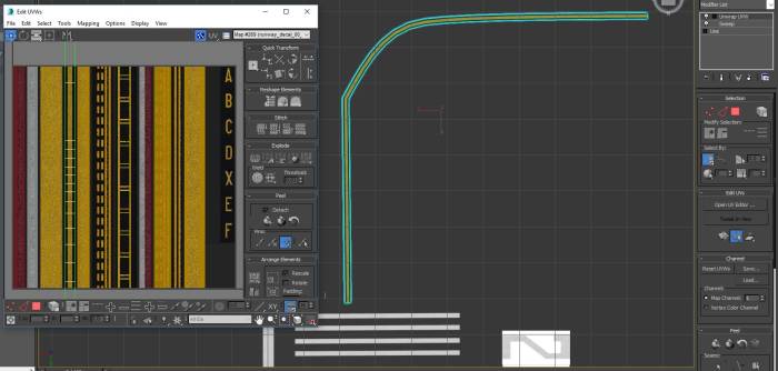
- Add a texture to your line the same way as before.Note you will need to straighten your line by using the “straighten selection” under reshape elements.
Since there are no other decals that go under this line, go ahead and attach it to the 'runway_decal__priority0' group. Click on the group in your hierarchy and click on the attach function and click on the line that you just created. Note We are adding this line to this group for the purpose of the tutorial, you can pick and choose which groupings you want your decals in.
Lets now make a 'hold short' decal that overlaps the centerline decal that you just made.
- select a plane and convert it to an editable poly.
- Adjust the plane's edges by clicking on the vertex and moving them to fit the contour of the taxiway edges.
- Add modifier unwrap UVW and add a texture the same way as before.
- Rename this decal to a higher priority. Let's name it: taxiway_decal (underscore underscore) priority1 This will show this decal on top of the taxiway center line that we previously made.
The final step of making decals will be to group each sub-group of decals that you made. So let's do this now.
- select runway_decal (underscore underscore) priority0 and taxiway_decal (underscore underscore) priority1 and click the group tab then group. Name this group ewy_keywest_decal note this naming can be whatever you want to name this group but the _decal must exist. This group and all of it's contents will be what you export into your airport project folder. The group name in the hierarchy must match exactly to what you have named in your TMC file.
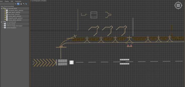
Here is an example of what your project should now look like once finished.
- Finally, select your entire decal group and export (export selected) it as an object into your airport project folder. You will see the TGI file created.
The final result of this project should show all three TGI files (_obj _rwy _decal), your TSC file, and all _color textures used in your project. Note all texture files must be 2080×2048.
Adding XREF Models
So your airport is finished but it still looks empty? We have published a large xref library of models that you can use to add already made aircraft, buildings, structures, and airport objects to your project easily.
The complete xref model library can be found in the Aerofly FS 2 Downloads section HERE
Let's add a couple of these now.
- First locate an area that you want to place an xref model
- Under helpers you will find an object called dummy, we will be using this object for placing any xref object into our project.
- select dummy and make a small cube where you want your model
- Search for the reference model that you want to place in your project. Take note of the xy positioning shown on the reference model image as this is how it will be aligned in-game. You can rotate the dummy cube to the direction that you wish and the model will be in that position when you see the model in Aerofly.
- Rename the dummy cube to exactly match the name of the xref model that you want to see. Note it's easiest to simply copy/paste the name.
- Finally add the dummy cube to your object _obj group. Right click/Add Selected To/New Parent (Pick) and click on your _obj group
Closing Remarks
Let's recap everything we have done.
- We have learned how to build the three needed export groups to properly build an airport
- We have learned how to create our TSC file
- We have learned some tips and tricks on how to perform certain tasks in 3DS Max
- We have added some xref models to our airport to make it look more active
Here is everything together (with the groundpoly turned off as it covers our area)
Now that we have our entire airport built it's time to convert the project into Aerofly.
Finally, there are many different techniques used to produce some very nice sceneries from 3DS Max, this tutorial shows only some very basic techniques. The key here is to practice but most importantly to enjoy yourself. It's a good feeling when you are sitting on the apron of your favorite airport that YOU created.
Enjoy!

![}
* Convert the “center” coordinate from the FSET job to decimal using the website [[https://rechneronline.de/geo-coordinates/|HERE]]. This will be the center of your reference image in 3DS Max and will also be your center coordinate in your TMC file
{{:wiki:tsc_coods_3_.jpg?700| }
* Convert the “center” coordinate from the FSET job to decimal using the website [[https://rechneronline.de/geo-coordinates/|HERE]]. This will be the center of your reference image in 3DS Max and will also be your center coordinate in your TMC file
{{:wiki:tsc_coods_3_.jpg?700|](/dokuwiki/lib/exe/fetch.php/wiki:reference_center_2_.jpg?w=700&tok=26b564)
