Table of Contents
Rigidbody-System
The most defining feature of an aircraft's behavior is its mass. Even without any air and without any aerodynamics or propulsion an aircraft would still travel as far as you can throw it. If it weren't for the gravitational pull it would would just keep moving and rotating for as long as there is no external force stopping it. This motion and rotation of a mass object can be represented mathematically which is how a flight simulator like Aerofly is able to calculate the movements of an aircraft.
For this mathematical description Aerofly needs to know a few key parameters of the objects it is simulating. Most important of all is the mass, which is represented in Kilograms. The mass defines how fast an object accelerates when a given force acts onto it. For example: If an aircraft is on the ground and the aerodynamic forces are neglitable then the acceleration of the aircraft is directly proportional to the thrust of the engine divided by the mass of the aircraft. Heavier aircraft with the same thrust will therefor accelerate much slower than light aircraft. And only if the total mass of the aircraft is set to a realistic value will the acceleration be realistic.
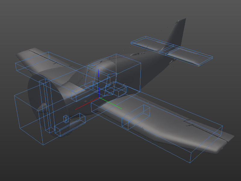
Here is a visualization of how all the rigidbodies of the DR400 aircraft:

Rigidbody
Aerofly uses the mathematical concept of a rigidbody to simulate the aircraft mass. A rigidbody in Aerofly can be thought of as a box with a certain size, a certain mass, position and orientation, velocity and angular velocity (rotation speed). Roughly speaking “a box that moves and rotates”.
We usually break down the aircraft into several parts, for example the left and right wings, the fuselage, stabilizer, propeller and individual parts of the landing gear (those that move independent of each other).
In the tmd file the rigidbody of the fuselage is defines like this:
            <[rigidbody][Fuselage][]
                <[float64][Mass][387.0]>
                <[tmvector3d][InertiaLength][ 4.0 1.116 1.08 ]>
                <[tmvector3d][R0][ 0.612 0.0 0.396 ]>
                <[tmmatrix3d][B0][ 1.0 0.0 0.0  0.0 1.0 0.0  0.0 0.0 1.0 ]>
            >
Let us break down each parameter:
Name
The name of the object is defined in the line of code <[rigidbody][Fuselage][]. Here it is set to Fuselage. This identifying name can only be used once and is used throughout the entire file to reference this rigidbody. Anywhere another object in the tmd uses Body or PositionID (or something similar) we can plug in a rigidbody name.
Mass
This is self explanatory. The mass of the rigidbody defines how fast an object accelerates with a given force acting on it. One of these forces could be gravitation. The force that we call weight is just the mass of an object multiplied by the gravitational constant (e.g. on Earth about 9.81 m/s²).
In the line <[float64][Mass][387.0]> we set the mass of the rigidbody to 387 Kilograms.
InertiaLength
With <[tmvector3d][InertiaLength][4.0 1.116 1.08]> we set the size of our rigidbody to 4m long, 1.116m wide and 1.08m high. The greater each of the values the higher the inertia of the object. With a given torque (e.g. torque of the engine) the inertia defines how fast the angular speed (rotation speed) of the object increases, in other words how high the rotational acceleration is. With higher values the rigidbody will resist any attempt of starting or stopping a rotation. This directly affects how agil the aircraft is in the simulation.
R0
R0 is the position of the body at simulation time zero, or if you neglect any movement of the parts then R0 is the position of the rigidbody relative to the aircraft's origin. <[tmvector3d][R0][0.612 0.0 0.396]> sets the center of mass of our rigidbody to 0.612m in front of the origin and 0.396m up. The y component is 0 because the fuselage mass for our symmetric aircraft should be exactly on the symmetry plane.
B0
B0 is a rotation matrix and represents the orientation of the body at simulation time 0, or if you neglect any bending what so ever then this is the orientation of the object relative to the orientation of the aircraft.
Most objects are aligned with the aircraft orientation so we can remove this line or explicitly leave the default value <[tmmatrix3d][B0][ 1.0 0.0 0.0 0.0 1.0 0.0 0.0 0.0 1.0 ]> in.
The B0 matrix is define in columns, in this case:
X = 1.0 0.0 0.0
Y = 0.0 1.0 0.0
Z = 0.0 0.0 1.0
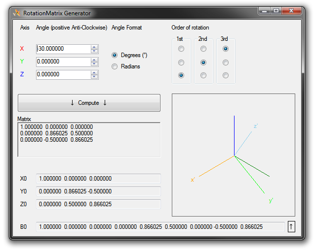
A recommended tool to generate the B0 rotation matrix has been published by one of our team members: Rotation Matrix Generator (use at own risk)
Joints
The individual rigidbodies of the aircraft are each simulated independently and there is no connection between them yet. Joints are used to connect rigidbodies together to create the flexible airframe. A joint can be thought of as a spring and damper system that creates a force and torque when two rigidbodies are moved or rotated relative to each other.
The spring force is the displacement multiplied by the spring constant “K”.
The damping force is the relative velocity times a damping constant “D”.
In the Aerofly FS 2 physics engine we have several joint types to chose from:
Multibody-Joint
A multibody_joint is a connection between two rigidbodies that allows only one new degree of motion. This means the two objects are coupled together very strongly and will move or rotate pretty much dependent of each other. (not independent!)
This joint is widely used in Aerofly FS 2, it constrains the movements of each part so that long chains like the actuated landing gear of an airliner become relatively easy to understand and set up and compute but still allowing complex movement. For example: The landing gear is rotated around one axis when it is retracted. But the lower part of the landing gear is not directly attached, it has a damper that dampens most of the shock when the aircraft touches down.
This is an example of the left wing's root joint. It is allows a rotation around the x-axis, which means the wing can still flap up and down but it can't freely move forward, left/right or up/down (without rotation) relative to the fuselage or rotate around any other axis. The values Kp and Kd are set quite high, since the wing creates a lot of lift and this joint has to transfer that bending torque around the root. It's a stiff connection that doesn't allow much movement:
Caution: Requires a rigidbody with the nameFuselageand another with the nameLeftWing
            <[multibody_joint][JointFuselageLeftWing][]
                <[string8][Body0][Fuselage]>
                <[string8][Body1][LeftWing]>
                <[tmvector3d][X0][ 1.0 0.0 0.0 ]>
                <[tmvector3d][R0][ -0.27 0.558 0.018 ]>
                <[float64][Kp][1000000.0]>
                <[float64][Kd][10000.0]>
                <[uint32][Type][0]>
            >
Type
There are two modes of this joint:
Type 0 allows the two bodies to only rotate relative to each other on one axis.
Type 1 allows the two bodies to move relative to each other along one axis.
X0
X0 is the rotation axis (type 0) or translation axis (type 1) of the joint connection. It is a unit vector.
R0
R0 is the rotation pivot (type 0) or attachment point (type 1) as a position in meters relative to the aircraft origin.
Kp
Spring constant in Newton-Meter per radiant = N*m/rad (type 0) or Newton per meter = N/m (type 1). Higher values mean the connection is stiffer and the torque/force created is much higher at small displacement.
Kd
Damping constant in Newton-Meter per radiant per second = N*m/(rad/s) (type 0) or Newton per meter per second = N/(m/s) (type 1). Higher values mean the connection is damped more and the torque/force created is much higher at small relative velocities.
Joint-Linear
Allows full 6 degrees of motion: 3 translation components and 3 rotational components.
Typical short version
Caution: Requires two rigidbodies with the namesFuselageandLeftElevator
            <[jointlinear][JointFuselageLeftElevator][]
                <[string8][Body0][Fuselage]>
                <[string8][Body1][LeftElevator]>
                <[tmvector3d][X0][ 1.0 0.0 0.0 ]>
                <[tmvector3d][Y0][ 0.0 1.0 0.0 ]>
                <[tmvector3d][Z0][ 0.0 0.0 1.0 ]>
                <[tmvector3d][R0][ 0.0 0.0 0.0 ]>
                <[float64][Kfx][100000000.0]>
                <[float64][Kfy][100000000.0]>
                <[float64][Kfz][100000000.0]>
                <[float64][Dfx][100000.0]>
                <[float64][Dfy][100000.0]>
                <[float64][Dfz][100000.0]>
                <[float64][Ktx][3000000.0]>
                <[float64][Kty][100000000.0]>
                <[float64][Ktz][100000000.0]>
                <[float64][Dtx][100000.0]>
                <[float64][Dty][100000.0]>
                <[float64][Dtz][100000.0]>
                <[float64][ForceMax][500000.0]>
                <[float64][TorqueMax][30000.0]>
            >
Full version
Caution: Requires two rigidbodies with the namesFuselageandLeftElevatorand some object with the nameServoElevatorand one with the nameServoRudder.
            <[jointlinear][JointFuselageLeftElevator][]
                <[string8][Body0][Fuselage]>
                <[string8][Body1][LeftElevator]>
                <[tmvector3d][X0][ 1.0 0.0 0.0 ]>
                <[tmvector3d][Y0][ 0.0 1.0 0.0 ]>
                <[tmvector3d][Z0][ 0.0 0.0 1.0 ]>
                <[tmvector3d][R0][ 0.0 0.0 0.0 ]>
                <[float64][Kfx][100000000.0]>
                <[float64][Kfy][100000000.0]>
                <[float64][Kfz][100000000.0]>
                <[float64][Dfx][100000.0]>
                <[float64][Dfy][100000.0]>
                <[float64][Dfz][100000.0]>
                <[float64][Ktx][3000000.0]>
                <[float64][Kty][100000000.0]>
                <[float64][Ktz][100000000.0]>
                <[float64][Dtx][100000.0]>
                <[float64][Dty][100000.0]>
                <[float64][Dtz][100000.0]>
                <[float64][ForceMax][500000.0]>
                <[float64][TorqueMax][30000.0]>
                <[string8][Rotation0Control][ServoElevator.Output]>
                <[tmvector3d][Rotation0Axis][ 0.0 1.0 0.0 ]>
                <[float64][Rotation0Angle][1.0]>
                <[string8][Rotation1Control][ServoRudder.Output]>
                <[tmvector3d][Rotation1Axis][ 0.0 0.0 1.0 ]>
                <[float64][Rotation1Angle][1.0]>
                <[tmvector3d][PreLoad][ 0.0 0.0 0.0 ]>
                <[tmvector3d][PreTension][ 0.0 0.0 0.0 ]>
                <[int32][Rigid][0]>
            >
Rigid
Setting Rigid to 1 instead of 0 will make this connection indestructible and completely solid. No translation or rotation will be possible and all parameter values are ignored.
R0
R0 is the attachment point
X0, Y0, Z0
X0, Y0 and Z0 define a rotation matrix to rotate the joint's axes. This is needed if the weakest axis is at a diagonal attitude.
Kf, Kt
All Kf values are spring constants in N/m that define the stiffness of the translation.
Kt are torsion damper constants.
Df
All Df values are damping constants in N/(m/s) that define the damping or the relative velocity
Dt are torsion damper constants.
ForceMax, TorqueMax
Defines the force and torque at which the connection breaks. From that moment on the two bodies are completely independant and the crash reset timer is started which reloads the aircraft after (default) 3 seconds.
Rotation Input
Using Rotation0Control, Rotation0Angle and Rotation0Axis one can define a connection that is actuated. Another rotation on the same joint can be made with the 'Rotation1Control, Rotation1Angle and Rotation1Axis.
PreLoad, PreTension
Defines the offset force (in Newtons) or torque (in Newton-Meters). When the deflection or displacement is zero this force or torque is still acting between the two bodies. Normally the landing gear would compress under the weight of the aircraft but the PreLoad parameter could reduce this displacement to zero on the ground. In the air the gear would then extend outward.
Joint-Torque
Only applies a torque between two bodies and doesn't restrict any of the other movement. This is mostly used in combination with a multibody_joint to simulate a drive shaft.
Caution: Requires two rigidbodies with the namesFuselageandPropellerBody
            <[jointtorque][DriveShaft][]
                <[string8][Body0][Fuselage]>
                <[string8][Body1][PropellerBody]>
                <[tmvector3d][Z0][ 1.0 0.0 0.0 ]>
                <[float64][Friction][0.0]>
            >

